# Current Sensor Hardware
| View | Top | Bottom |
|---|---|---|
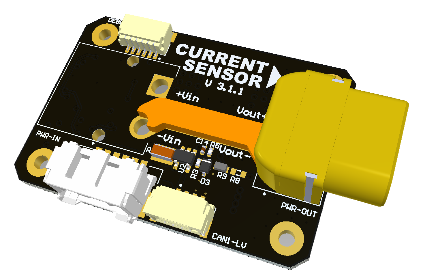 | 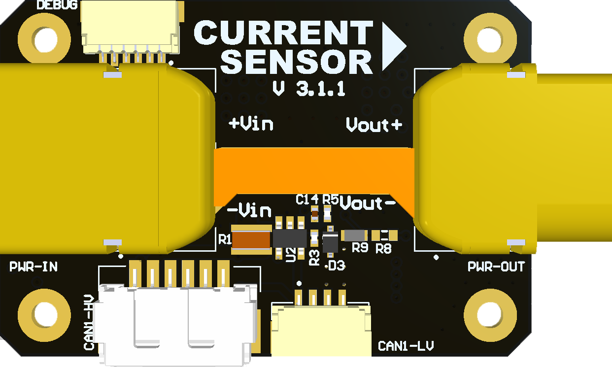 | 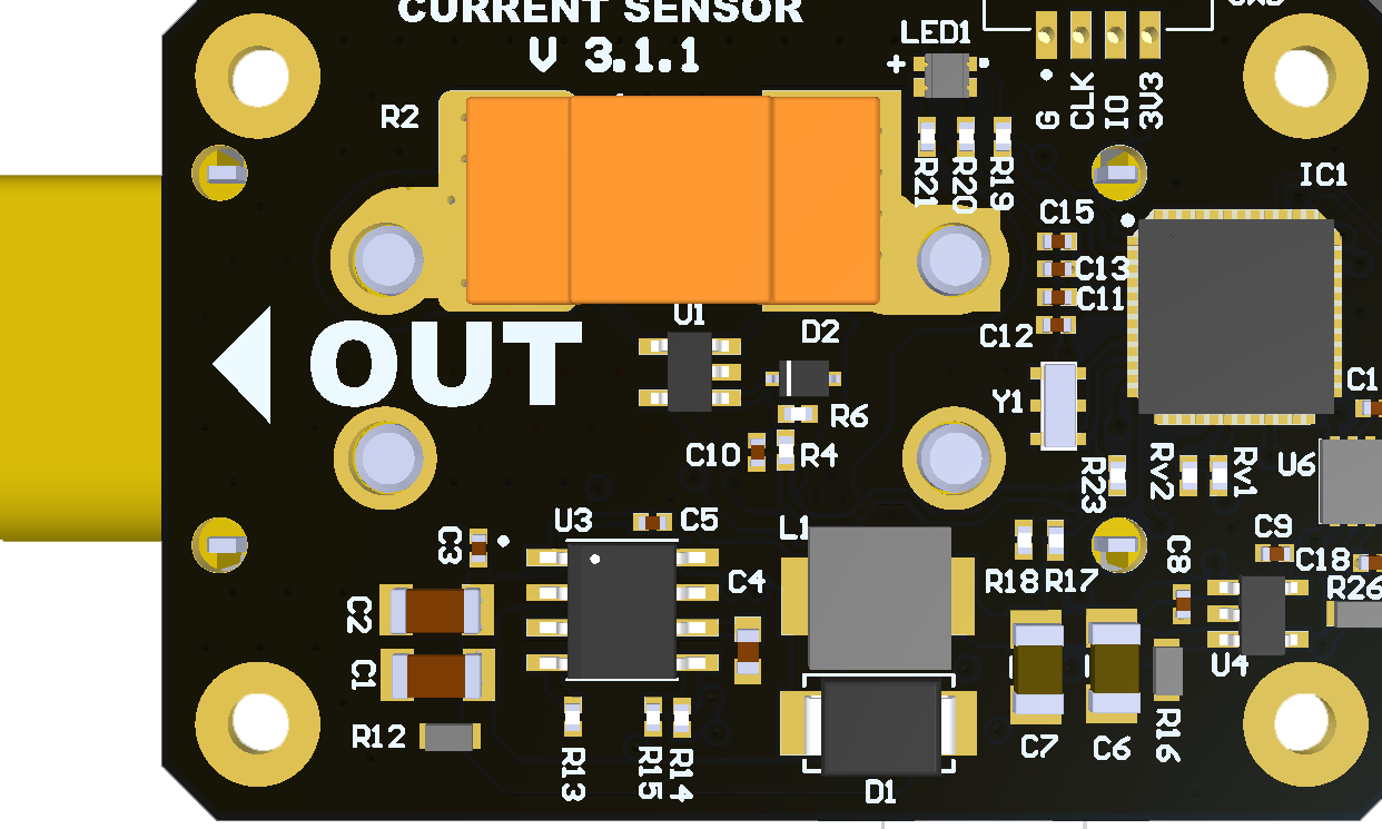 |
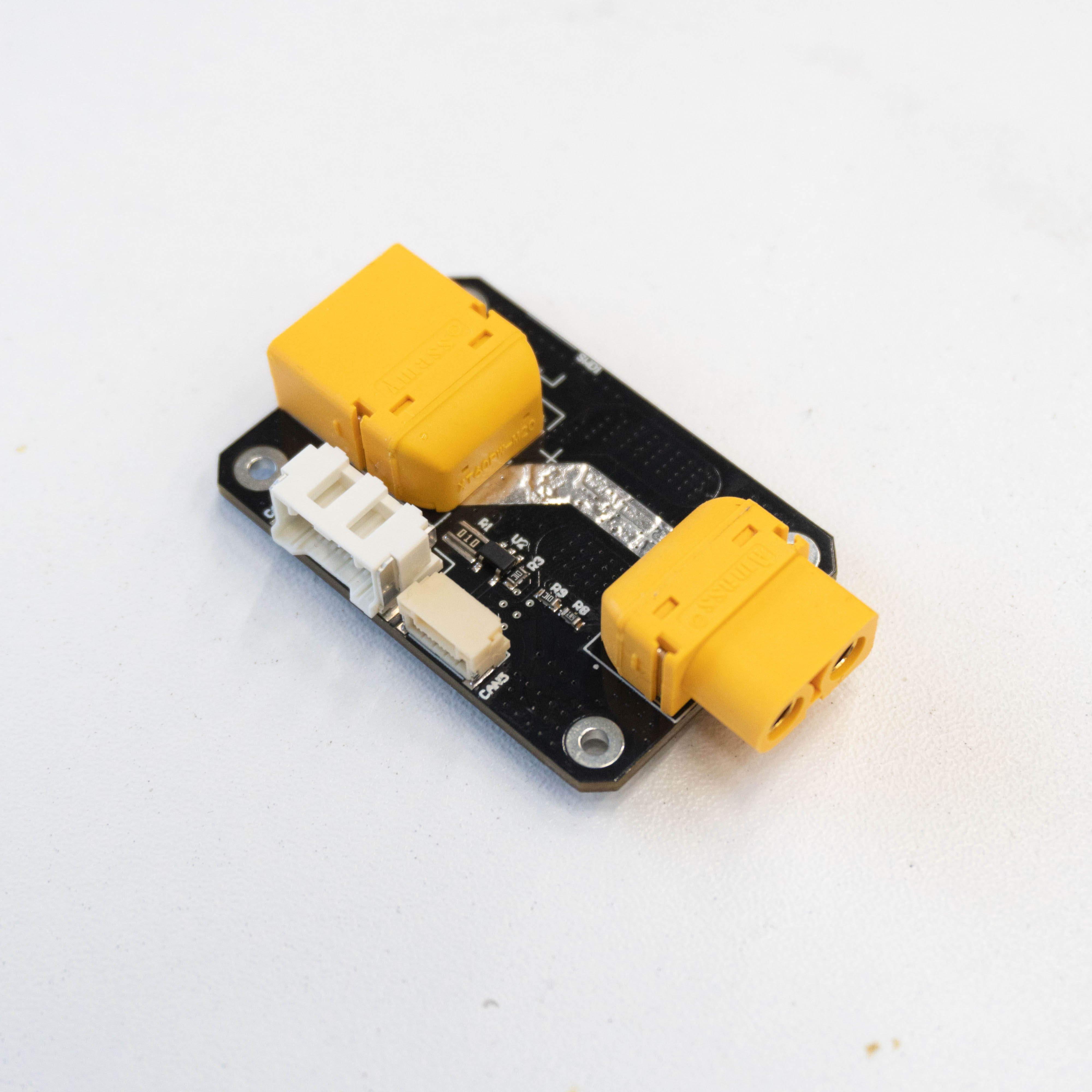 | 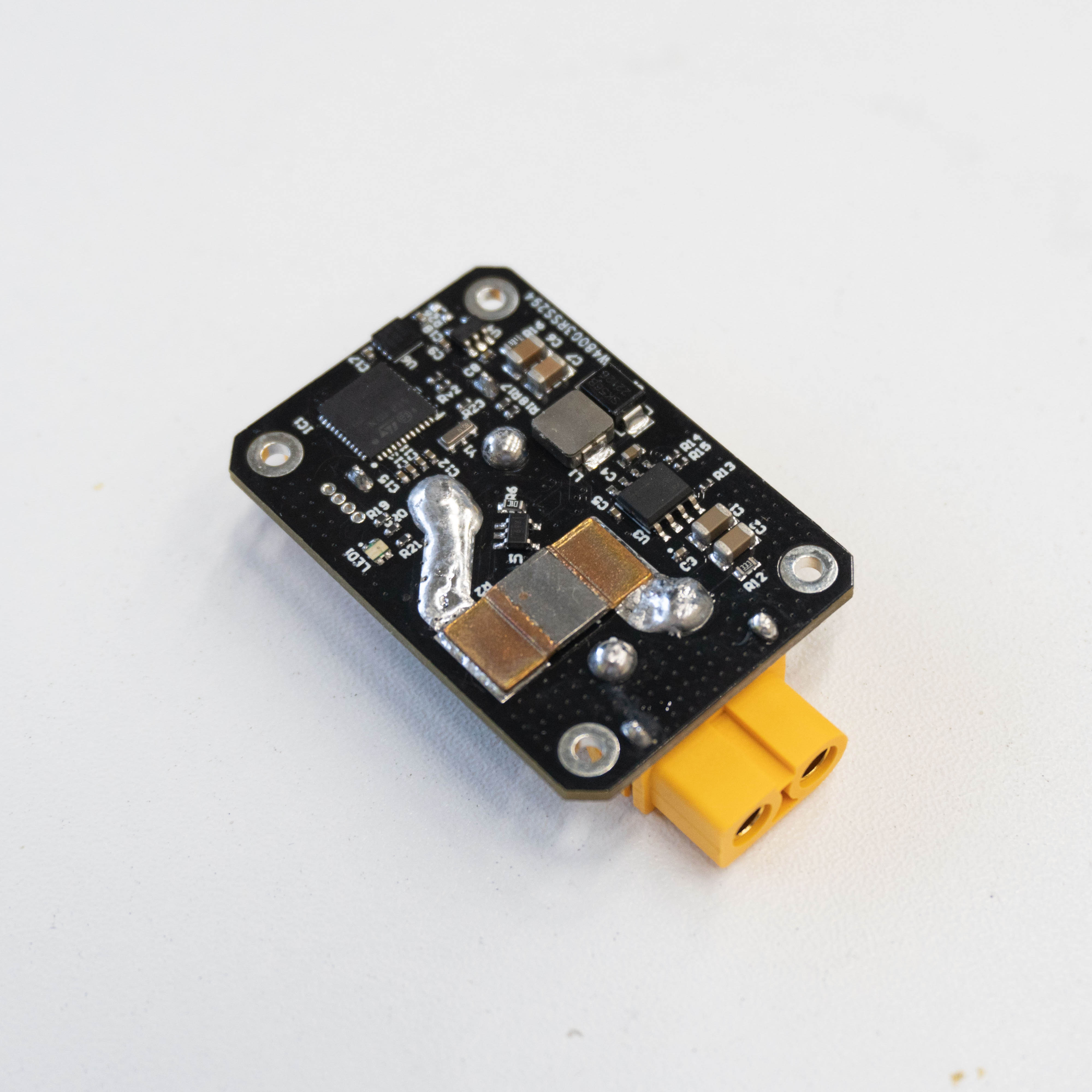 |
# Features
- Support 5.5~30V voltage input
- Maximum passing current 60A
- Measurement current accuracy 0.2
- Мoltage accuracy 0.15V
- Regulated output provide up to 13W 5.5V/2.5A output
- LED indicator
# Wiring
Schematic features. Schematic can be provided via issue.
Connectors
The node has connectors which are described in the table below.
| N | Connector | Description |
|---|---|---|
| 1 | CAN1 | Supply the power line with Vin voltage and provide the CAN bus. |
| 2 | CAN5 | Provide CAN bus and regulated 5.5V power |
| 3 | PWR-IN | XT60 connector for input voltage |
| 4 | PWR-OUT | XT60 female connector for payload connection |
| 5 | SWD1 | Firmware update port |
Here you can find manufacturer part number of connectors it self and its mates.
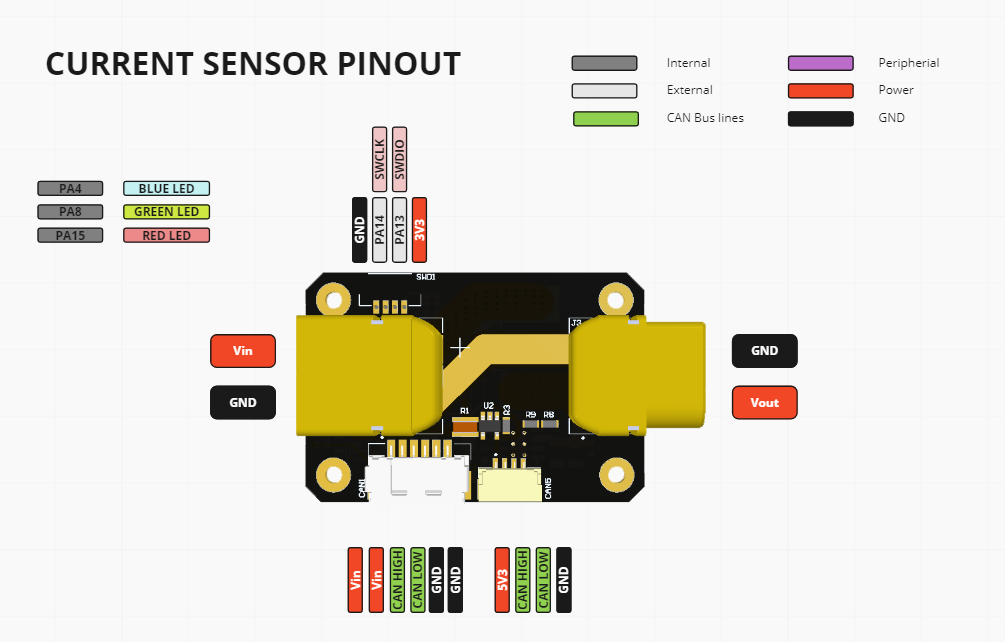
# Pin configuration and functions
| Pin N | CAN1 | Pin N | CAN5 | Pin N | PWR-IN | Pin N | PWR-OUT | Pin N | SWD1 |
|---|---|---|---|---|---|---|---|---|---|
| 1 | Vcan | 1 | 5V | 1 | Vbat | 1 | Vin | 1 | GND |
| 2 | Vcan | 2 | CAN_H | 2 | GND | 2 | GND | 2 | SWLK |
| 3 | CAN_H | 3 | CAN_L | 3 | SWDIO | ||||
| 4 | CAN_L | 4 | GND | 4 | 3.3 | ||||
| 5 | GND | ||||||||
| 6 | GND |
Here you can see all connections of MCU.
| MCU PIN | PIN Numer | NET Name | Description |
|---|---|---|---|
| PA7 | 18 | ADC_VERSION | Version devider connected here |
| PA14-BOOT0 | 36 | SWLK | |
| PA13 | 35 | SWDIO | |
| PF2-NRST | 10 | STM_NRST | |
| PF1-OSC_OUT | 9 | OSC_OUT | 8 Mhz XTAL |
| PF0-OSC_IN | 8 | OSC_IN | 8 Mhz XTAL |
| PC13 | 1 | INTERNAL_LED_RED | |
| PC15-OSC32_OUT | 3 | INTERNAL_LED_BLUE | |
| PC14-OSC32_IN | 2 | INTERNAL_LED_GREEN | |
| PB2 | 21 | ADC_CAN_CURRENT | Measurement of the current passing through the CAN1 port |
| PD1 | 39 | FDCAN1_TX | |
| PD0 | 38 | FDCAN1_RX | |
| PA0 | 11 | ADC_VIN | Measurement of the voltage on Vin |
| PA6 | 17 | ADC_CURRENT | Measurement of the current passing through the PWR-OUT port |
| PA1 | 12 | ADC_5V | Measurement of the voltage on 5V power line |
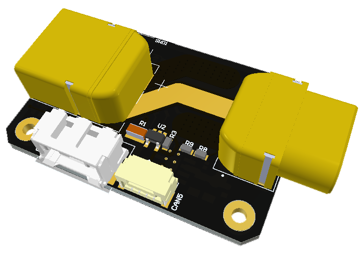
# Specifications
Mechanical
Scheme is shown on the picture below. model can be provided via email request or issue on github or downloaded on GrabCAD (opens new window).
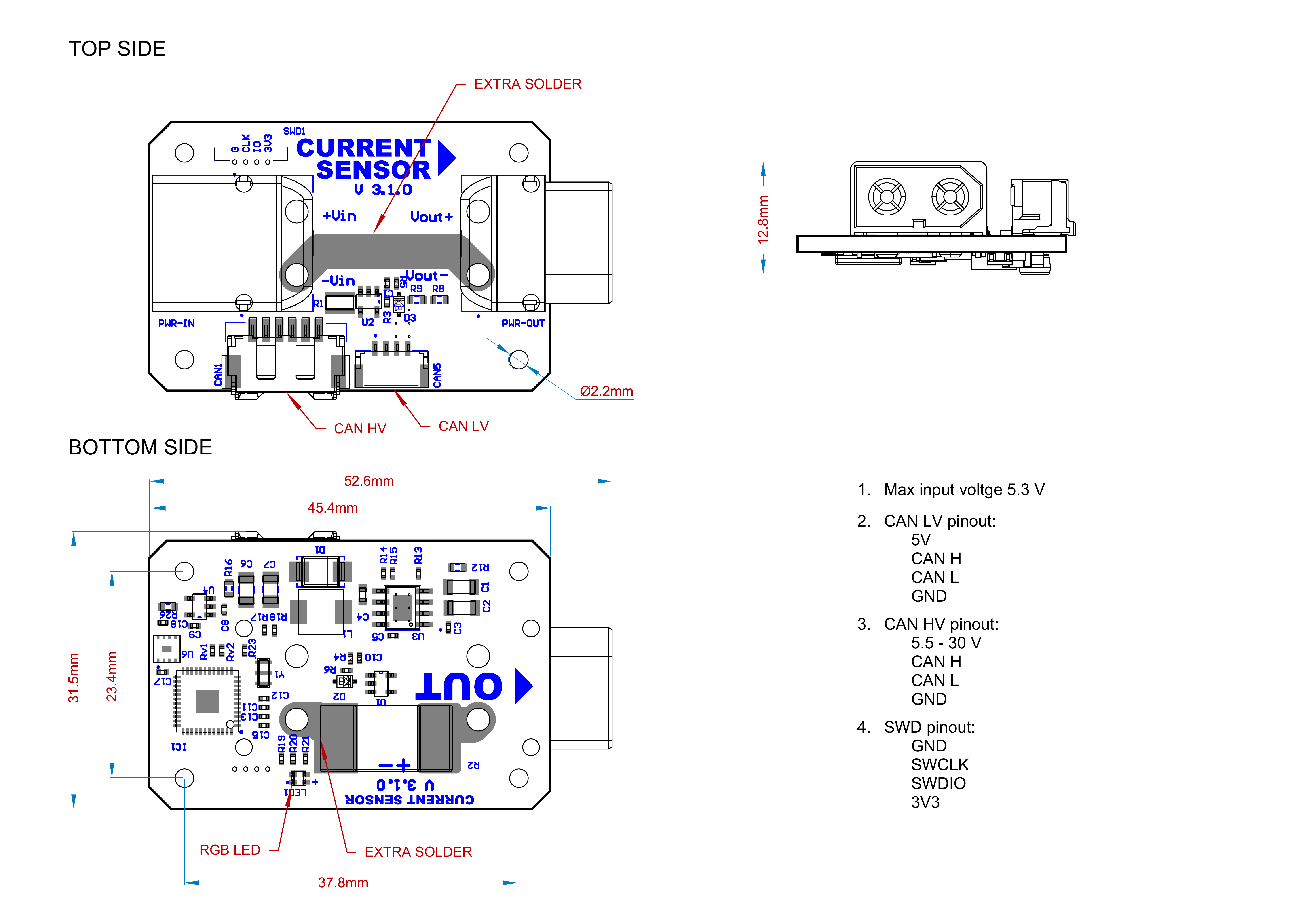
| Width, mm | Length, mm | Height, mm | |
|---|---|---|---|
| Outline | 52.4 | 31.6 | 12.8 |
| PCB | 45.4 | 30.7 | 2.0 |
Total weight of device less than 50 g.
# Housing
Information about case presented here.
# Electrical
| Parameter | Value |
|---|---|
| Input voltage | 5.5-30V (Up to 50 V) |
| Maximum current | 60A |
| Voltage accuracy | ±0.15V |
| Current accuracy | ±0.2A |
| Resolution | 0.01A/V |
| 5V regulated output | 2.5A max |
# Absolute Maximum Ratings
| Parameter | MIN | MAX | UNIT |
|---|---|---|---|
| Vin (CAN1) | 5.5 | 55* | V |
| V (CAN5) | 4.5 | 5.5 | V |
| I max | A | ||
| Operating temperature |
*Noted Voltage should be delivered only with current limitation under 2.5 Amp.
# Recommended operating conditions
| Parameter | Value | UNIT |
|---|---|---|
| Vin (CAN3) | 30 | V |
| V (CAN5) | 5 | V |
| I max | A |
# ESD ratings
| Description | Value | UNIT |
|---|---|---|
| Human-body model (HBM) | 2000 | V |
| Charged-device model (CDM) | 500 | V |
# MTFF
# Integration
Recommended mechanical mounting
There are no specific recommendations.
Connection example diagram

# Power Supply Recommendations
Device is designed to operate from an input voltage supply range between 4.5 V and 5.5 V over CAN2 or CAN3 connector, or 5.5 - 30 V from CAN1. This input supply must be able to withstand the maximum input current and maintain a stable voltage. The resistance of the input supply rail should be low enough that an input current transient does not cause a high enough drop that can cause a false UVLO fault triggering and system reset. The amount of bulk capacitance is not critical, but a 47-uF or 100-uF electrolytic capacitor is a typical choice.
# Revision history
| View | Version | Date | Description |
|---|---|---|---|
 | v3.1.0 | 12 Oct 2022 | init |
| v3.1.1 | 1 Sep 2024 | hardware mistakes fixed, debug connector added, voltage signal line moved away from coil |