# DroneCAN Internal Combustion Engine node
This board is dedicated to controlling an internal combustion engine such as DLE-20 (opens new window) or DLE-35 (opens new window) using Electronic Ignition Module.
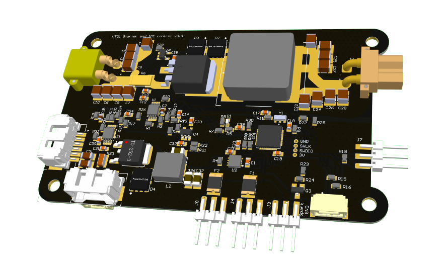
Based on input command RawCommand (opens new window) it activates ignition, starts a starter to run the engine and turn the starter off when the internal combustion engine is working. It measures several engine parameters such as engine rotation speed and sends it to UAVCAN network as uavcan.equipment.ice.reciprocating.Status (opens new window) message. It also might be equipped with fuel tank sensor based on differential pressure sensor, so the node will send uavcan.equipment.ice.FuelTankStatus (opens new window) message.
# 1. DroneCAN interface
This node interacts with the following messages:
№ | type | message |
---|---|---|
1 | subscriber | uavcan.equipment.esc.RawCommand (opens new window) |
2 | publisher | uavcan.equipment.ice.reciprocating.Status (opens new window) |
3 | publisher | uavcan.equipment.ice.FuelTankStatus (opens new window) |
Besides required and highly recommended functions such as NodeStatus
and GetNodeInfo
this node also supports the following application-level functions:
№ | type | message |
---|---|---|
1 | RPC-service | uavcan.protocol.param (opens new window) |
2 | RPC-service | uavcan.protocol.RestartNode (opens new window) |
3 | RPC-service | uavcan.protocol.GetTransportStats (opens new window) |
# 2. Hardware specification
(in work)
# 3. Wire
This board has 4 connectors which may deliver a power to this device. They are described in the table below.
№ | Connector | Description |
---|---|---|
1 | Power socket (XT30) | This board consumes more power than a typical UAVCAN node, so it is powered using an additional socket. |
2 | UCANPHY Micro (JST-GH 4) | Devices that deliver power to the bus are required to provide 4.9–5.5 V on the bus power line, 5.0 V nominal. Devices that are powered from the bus should expect 4.0–5.5 V on the bus power line. The current shall not exceed 1 A per connector. |
3 | 6-pin Molex (502585-0670 (opens new window), 502578-0600 (opens new window)) | Contacts support up to 100 V, 2 A per contact. But the board may work only with 2S-6S. |
4 | SWD | STM32 firmware updating using programmer-sniffer. |
It also has following board-specific connectors:
№ | Connector | Description |
---|---|---|
5 | Fuel tank sensor based on MS4525DO | i2c |
6 | Starter | GPIO output pin |
7 | Spark ignition | GPIO output pin |
8 | Gas throttle | PWM with frequency 50 Hz and duration from 900 to 2000 |
9 | Air throttle | PWM with frequency 50 Hz and duration from 900 to 2000 |
10 | RPM sensor | Input capture |
11 | Temperature sensor | One-wire |
# 4. Main function description
On the input the node has RawCommand (opens new window) message.
The node controls 3 devices: Starter
, Spark Ignition
and Gas Throttle
. The control of these devices is performed in their own task, it means their logic are independent from each other.
Internally, the node has a safety mechanism called kill-switch. If the setpoint is not appear for 2 seconds, it will automatically change the state of each devices to default.
# 4.1. Gas throttle
Gas throttle is responsible for thrust created by an engine. The output PWM is linearly controlled by RawCommand. The lower and higher borders of duration are defined in corresponding parameters. Check corresponded parameters in the section 6.5. Gas throttle.
# 4.2. Air throttle
The main function of the air throttle is to supply and regulate the air flow necessary for the formation of the air-fuel mixture.
Typically, we want a bit less air during the starting the internal combustion engine. It is more fuel costly, but the motor may start easilier. Let's call it the initial
throttle position.
When the motor is already working, we want to maintain a constant optimal fuel to air ratio. In simplest case it might be just another throttle value called goal
.
The idea of the suggested air throttle algorithm is to linearly open the air throttle from the initial
to the goal
state for a specific period of time and keep it until the new starter iteration starts.
Although the default goal
state is specified in parameters, an operator may specify the actual goal
value in real time during preflight checks using ArrayCommand
message with the index specified in parameters.
# 4.3. Spark Ignition
Spark Ignition allows to enable or disable engine. It is controlled by a simple GPIO output pin that has 2 states. If the value of RawCommand of the corresponding channel is higher than some offset, it will be enabled. Otherwise it will be disabled. Check corresponded parameters in the section 6.2. Spark ignition.
# 4.4. Starter
Starter allows to automatically run an engine. It is implemented as GPIO output pin, so it has 2 states. If the input channel value is greater than the offset, it will perform an attempt to run an engine with a duration up to a certain time. If an attempt is unsuccessful, it will turn off for a certain time (to signalize that it's unsuccessful), and then try again. If the median speed for last second is greater than some certain value it will stop attempts. Durations and offsets can be set up in parameters. Check corresponded parameters in the section 6.3. Starter
# 4.5. RPM measurement
This sensor is based on hall-sensor. It counts the number of impulses for the last short period of time, filtrate the data, fills the uavcan.equipment.ice.reciprocating.Status (opens new window) message and sends it.
# 4.6. TTL
For the safety reasons, if there is no RawCommand for last cmd_ttl_ms
milliseconds, the node will set all controlled values to the default states. It means, that that Starter will be turned off, Spark Ignition will be disabled and Gas Throttle will be in the default position according to the specified in parameters value.
# 5. Auxiliary functions description
# 5.1. Circuit status
This node as well as any other our nodes measure 5V
and Vin
voltages and send them in 2 uavcan.equipment.power.CircuitStatus (opens new window) messages.
These voltages might be visualized using our custom custom uavcan_gui_tool (opens new window).
The first message has circuit_id=NODE_ID*10 + 0
and following 3 significant fields:
- voltage - is the 5V voltage
- current - is the max current for the last 0.5 seconds (supported only by
5A
node) - error_flags - might have ERROR_FLAG_OVERVOLTAGE or ERROR_FLAG_UNDERVOLTAGE or non of them
The second message has circuit_id=NODE_ID*10 + 1
and following 3 significant fields:
- voltage - is the Vin voltage
- current - is the average current for the last 0.5 seconds (supported only by
5A
node) - error_flags - ERROR_FLAG_UNDERVOLTAGE or non of them. There is no ERROR_FLAG_OVERVOLTAGE flag because the expected max Vin voltage is unknown.
# 5.2. Node info
Every firmware store following info that might be received as a response on NodeInfo request. It stores:
- software version,
- an unique identifier.
# 5.3. Log messages
(will appear in further versions of software)
# 5.4. Watchdog
The node constantly performs updating watchdog values. If update is not happen for at least 0.5 seconds, it cause a hardware reset of microcontroller. This feature allows a node to leave a hang state if it is happen.
# 5.5. Stats recorder
The node automatically stores few parameters into the flash memory. Since writing to the flash is time consuming operation that may affect of performance, the saving request is called only after a short amount of time after disarm.
flight_time_sec
parameter keeps overall time during ARM,ice_time_sec
parameter keeps overall time when internal combustion engine is enabled.
You might be interesting in checking the last parameter to be sure that the lift engine operation time has not expired.
# 6. Parameters
Below you can see a picture from gui_tool
with a whole list of parameters.
All paramters are divided into several groups. Their description is provided in the tables below.
# 6.1. Common parameters
Following parameters are common for any nodes.
№ | Parameter name | Reboot required | Description |
---|---|---|---|
0 | ID | true | Node ID |
20 | err | false | If something unexpected goes wrong, the node writes code of occurred error into this value, save it and reboot. The node will continue to function, but it will keep ERROR status until this value is manually cleared. Normally, this value should be always zero. If it is not, you may contact us. |
21 | name | true | Unused. Reserved. In future the node name will might be configured using this parameter. |
# 6.2. Spark ignition
№ | Parameter name | Reboot required | Description |
---|---|---|---|
1 | spark_ignition_offset | false | If raw command more than that value, spark ignition will be turned on, otherwise turned off |
2 | spark_ignition_ch | false | Index of RawCommand channel; -1 means disable this feature |
# 6.3. Starter
№ | Parameter name | Reboot required | Description |
---|---|---|---|
3 | starter_offset | false | If RawCommand more than that value, spark ignition will be turned on, otherwise turned off |
4 | starter_ch | false | Index of RawCommand channel; -1 means disable this feature |
5 | starter_rpm_treshold | false | Starter might be turned on only if rpm less then that value |
6 | starter_try_duration | false | Period in milliseconds during which the starter will try to run the engine |
7 | starter_delay_before_next_try | false | Period in milliseconds during which the starter will wait between attempts |
# 6.4. ESC status
№ | Parameter name | Reboot required | Description |
---|---|---|---|
8 | esc_pub_period | false | Period between EscStatus publication. It has info about starter voltage and current |
9 | esc_index | false | Index of corresponded EscStatus message; -1 means disable publication |
# 6.5. Gas throttle
№ | Parameter name | Reboot required | Description |
---|---|---|---|
10 | gas_throttle_ch | false | Index of RawCommand channel; -1 means disable this feature |
11 | gas_throttle_min | false | PWM duration corresponded to RawCommand=0 |
12 | gas_throttle_max | false | PWM duration corresponded to RawCommand=8191 |
13 | gas_throttle_default | false | PWM duration corresponded to RawCommand < 0 or when there is no RawCommand for last half second |
# 6.6. Circuit status
№ | Parameter name | Reboot required | Description |
---|---|---|---|
14 | enable_5v_check | false | Set ERROR status if 5V voltage is out of range 4.5 - 5.5 V |
15 | enable_vin_check | false | Set ERROR status if Vin voltage is less than 4.5 V |
# 6.7. Motor speed measurement filter
It is expected that motor generates a single PWM impulse each rotation.
The algorithm increments a specific variable each time when an impulse occurred.
With frequency specified in rpm_measurement_frequency
parameter it calculate a difference between previous and current number of impulses and multiply it by 60 to get the raw value of RPM. The frequency should be at least twice less than idle rotations per second of the motor. For an example, for a motor with IDLE speed 1200 RPM, the parameter might be set to 10 or lower.
Optionally, you can specify rpm_moving_avg_filter_size
other than 1 to enable moving average filter. This is the easiest, fastest and less memory consumption filter algorithm to make RPM readings smoother. The default value has no effect on readings.
# 7. Led indication
This board has an internal led that may allow you to understand possible problems. It blinks from 1 to 10 times within 4 seconds. By counting the number of blinks you can define the code of current status.
Number of blinks | Uavcan health | Description |
---|---|---|
1 | OK | Everything is ok. |
2 | OK | There is no RawCommand at least for the last 0.5 seconds (it's not a problem for this board, just in case). |
3 | WARNING | This node can't see any other nodes in UAVCAN network, check your cables, or there is no incoming data from the sensor. |
4 | ERROR | There is a problem with circuit voltage, look at circuit status message to get details. It may happen when you power it from SWD, otherwise, be careful with the power supply. This check might be turned off using params. |
5 | CRITICAL | There is a problem with the periphery initialization level. Probably you load the wrong firmware. |
# 8. Debugging on a table
(in progress)
# 9. PX4 integration
This node has been successfully tested on VTOL. Here is an example of RPM and RawCommand values collected from one of the flight logs.