# 1. GNSS Mag Baro
The node is designed for light unmanned aerial (UAV) and other vehicles.
It has 3 types of sensors:
- GNSS module: u-blox L1 NEO-M8 (opens new window) or L1/L2 ZED-F9P (opens new window)
- Barometer: BMP280 (opens new window)
- Magnetometers: RM3100 (opens new window) and/or HMC5883L (opens new window)
The node supports 2 interfaces. Please refer the corresponded section for details:
# 1.1 Variations
There are different types of such GNSS magnetometer barometer nodes. They are illustrated below.
| L1/L2 ZED-F9P | L1/L2 ZED-F9P With external antenna | L1 NEO-M8N | MAGNETOMETER |
|---|---|---|---|
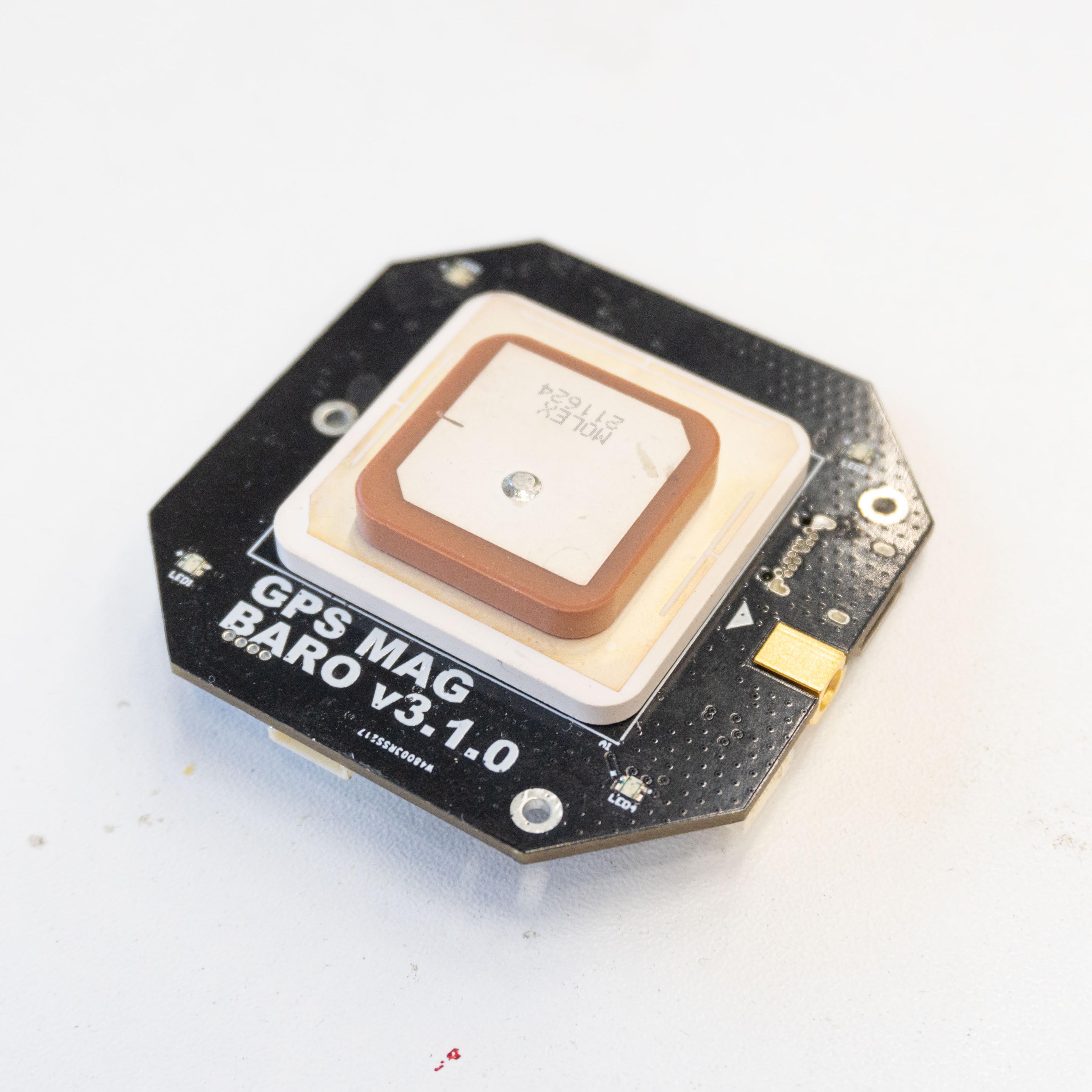 | 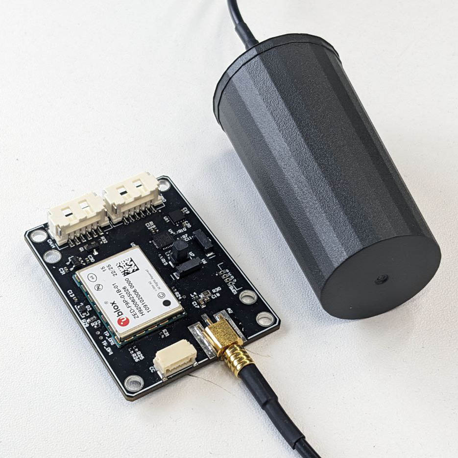 | 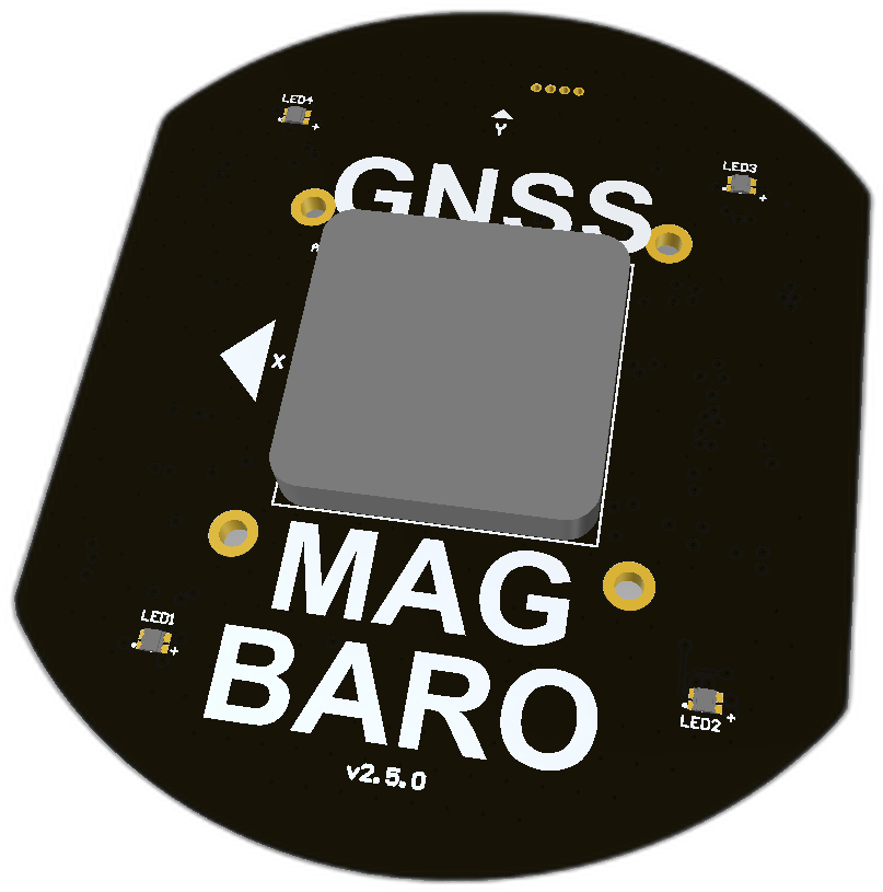 | 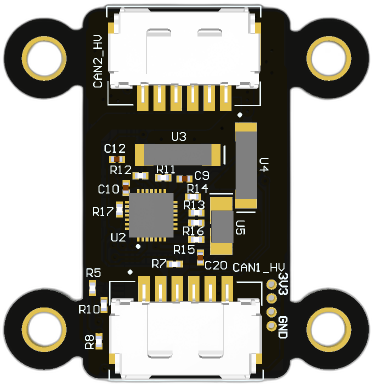 |
- L1/L2 RTK GNSS ZED-F9P is the top variant of GNSS module. Using this module you can get high accuracy of global coordinates and magnetic field data.
- L1/L2 RTK GNSS ZED-F9P With external antenna same GNSS module but reduced to use with external antenna only.
- L1 GNSS NEO-M8N is just common variant of GNSS module self powered with built-in DC-DC and communicates over CAN bus.
- MAGNETOMETER RM3100 is just magnetometer variation of the same board.
# 1.2 Main function description
This node primary has 3 features: GNSS, magnetometer and barometer. You may select in real time which features you need using Cyphal registers or DroneCAN parameters.
Below general features of the node are listed. For interface specific details please check 3. Cyphal interface or 4. DroneCAN interface.
# 1.2.1 GNSS module
If this feature is enabled, the node will receive the data from GNSS via UART (the communication protocol is ublox (opens new window), expected messages are NavPvt, NavCov, NavStatus) and send it to CAN as DroneCAN message or set of Cyphal messages depending on which interface you use.
GNSS module works with baudrate 921600.
At this moment you need to manually set up the ublox module before first use. Below you can see the instructions how to setup it.
# Performance
The raw GNSS-module needs 1 ms to send a UbxNavPvt package via UART (the baud rate is 921600, a package length is 100 bytes).
This board as a wrapper under GNSS-module needs less than 4 ms to serialize this package and send to CAN-bus.
The publishing frequency of uavcan.equipment.gnss.Fix2 (opens new window) depends on the publishing rate of UbxNavPvt, so it can change from 10 to 1 Hz depending on NEO-M8N (opens new window).
# 1.2.2 Barometer
The node uses BMP280 (opens new window) barometer. Communication with the sensor is carried out using I2C.
Control measurement settings:
- pressure oversampling is 8: high resolution, 19 bit / 0.33 Pa
- temperature oversampling is 8: 19 bit / 0.0006 °C
- the data rate is up to 50 Hz if standby time is less then 0.5 ms
- normal mode
# 1.2.3 Magnetometer
The node supports 2 types of magnetometers: RM3100 (opens new window) and HMC5883L (opens new window). You may choose the one you need at runtime using parameters.
Before the first measurement, this node performs initialization for the chosen magnetometer. Configuration settings are predefined in firmware and shown in the table below.
- i2c bus,
- Continuous-Measurement Mode with Normal measurement configuration,
- the measurement rate is 30 Hz (15 Hz is the default),
- adjustable publish rate up to 30 Hz using parameter,
- number of samples is 2 (1 is the default),
- the sensor field range is ± 1.3 Ga (by default), so digital resolution is 0.92 mG/LSb.
- SPI bus
- Continuous Measurement Mode,
- the measurement rate is 75 Hz (37 Hz is the default),
- adjustable publish rate up to 75 Hz using parameter,
- cycle count is 200 (by default), so the gain is 75 LSB/µT, sensitivity is 13 nT,
- field Measurement Range is from -800 to +800 uT.
# 1.3 Auxiliary functions description
The node has an internal RGB led that may allow you to understand possible problems. Please refer to LED meaning page to get more details.
# 1.4 Software update
The node doesn't yet support software upload via CAN yet. But the next generation of the device will be. We will be using a Kocherga bootloader (opens new window) in the future. At the moment the only way to upload the software is to use a programmer. See the programmer usage section (opens new window) for details.