# CAN-WiFi Sniffer
WiFi Sniffer is dedicated to wireless sniffering Cyphal/DroneCAN networks. It establishes connection between CAN-network using one of 2 CAN connectors from the one side and specified WiFi network through UDP from the other side.
It might be a safer alternative for wire CAN sniffer (opens new window).
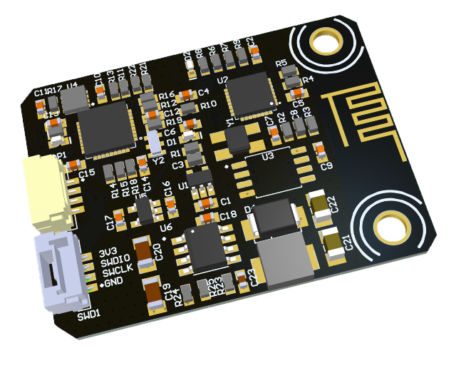
Below you can see an illustration of the board.
# 1. DroneCAN interface
This node doesn't send any specific messages.
Besides required and highly recommended functions such as NodeStatus and GetNodeInfo this node also supports the following application-level functions:
| № | type | message |
|---|---|---|
| 1 | RPC-service | uavcan.protocol.param (opens new window) |
| 2 | RPC-service | uavcan.protocol.RestartNode (opens new window) |
| 3 | RPC-service | uavcan.protocol.GetTransportStats (opens new window) |
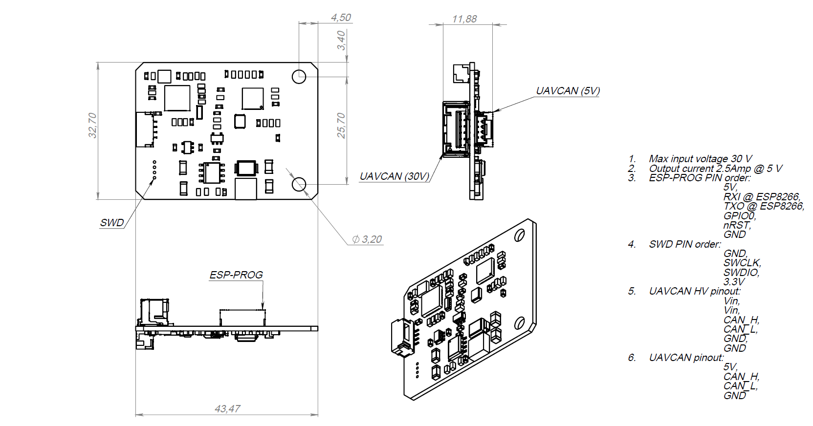
# 2. Hardware specification
The board v2.0 has following scheme:
# 3. Wire
This board has 4 connectors which are described in the table below.
| № | Connector | Description |
|---|---|---|
| 1 | UCANPHY Micro (JST-GH 4) | Devices that deliver power to the bus are required to provide 4.9–5.5 V on the bus power line, 5.0 V nominal. Devices that are powered from the bus should expect 4.0–5.5 V on the bus power line. The current shall not exceed 1 A per connector. |
| 2 | 6-pin Molex (502585-0670 (opens new window), 502578-0600 (opens new window)) | Contacts support up to 100 V, 2 A per contact. But the board may work only with 2S-6S. |
| 3 | SWD | STM32 firmware updating using programmer-sniffer. |
| 4 | esp8266 connector | Esp8266 firmware updating using usb-uart converter. |
# 4. Main function description
This node is dedicated for remote configuration UAVCAN network nodes or logging data stream.
Note: Because of performance limitation this node is not suitable for applications which require fast response such as controlling motors.
# 5. Auxiliary functions description
Software version
GetNodeInfo response contains software version that allows you to differentiate one firmware from another. See Node Properties window in uavcan gui tool.
Hardware version
Not implemented yet.
Hardware unique ID
GetNodeInfo response contains hardware unique ID that allows you to differentiate one board from another. See Node Properties window in uavcan gui tool.
Restart
By sending uavcan.protocol.RestartNode (opens new window) request this node might be restarted.
GetTransportStats
By sending uavcan.protocol.GetTransportStats (opens new window) request this node will response the message with number of transmitted and received frames.
# 6. Parameters

# 7. Led indication
This board has 2 LEDs. One in dedicated to the STM32 microcontroller, another one is for ESP8266.
Both LEDs allow you to understand possible problems. They blink from 1 to 5 times for 2 seconds, then wait for 2 seconds. By counting the number of blinks you can define the code of current status.
STM32 blinks meaning:
| Number of blinks | Uavcan health | Description |
|---|---|---|
| 1 | OK | UART and CAN are receiving and working |
| 2 | WARNING | There is no RX data from uart |
| 3 | WARNING | There is no RX data from CAN |
| 4 | WARNING | There is no RX data at all |
| 5 | CRITICAL | There is a problem with the periphery initialization level. Probably you load the wrong firmware. |
# 8. Usage example on a table
Below you can see an example of bus monitor plot with connected device that was published with frame rate 1500 frames per second.

# 8.1. How to debug it
You can see the debug messages by connection to the board via USB port. The debug messages might be obtain by any serial monitor programs. An example for ubuntu based on minicom utility shown below:
sudo apt-get install minicom
- By typing
sudo minicom -sand choosingSerial port setupconfigure 1000000 baud rate for your serial port, let's sayttyUSB0. - Don't forget to press
Save setup as dfl - Press
Exitand it will go into monitor mode
# 9. UAV usage example
WiFi sniffer has been tested several times with complex VTOL and other application.

# 10. Performance
This board has following performance characteristics:
- The response time up to 1 ms for each WiFi client.
- Maximum bandwidth is 3703 frames per second.
The response time is limited by time required for ESP8266 to send an UDP package. The bandwidth is limited by UART frequency that is 1000000 bit/sec. According to SLCAN each CAN frame is encoded into up to 27 bytes. So, maximum frame rate is 3703 frames per second.
# 11. How to upload firmware
Upload firmware to STM32 using SWD connector.
Upload firmware to ESP8266 using UART connector.
Choose an appropriate parameters before uploading.
| № | Hardware version | First | Second |
|---|---|---|---|
| 1 | Tools/Crystal Frequency | 26 MHz | 40 MHz |