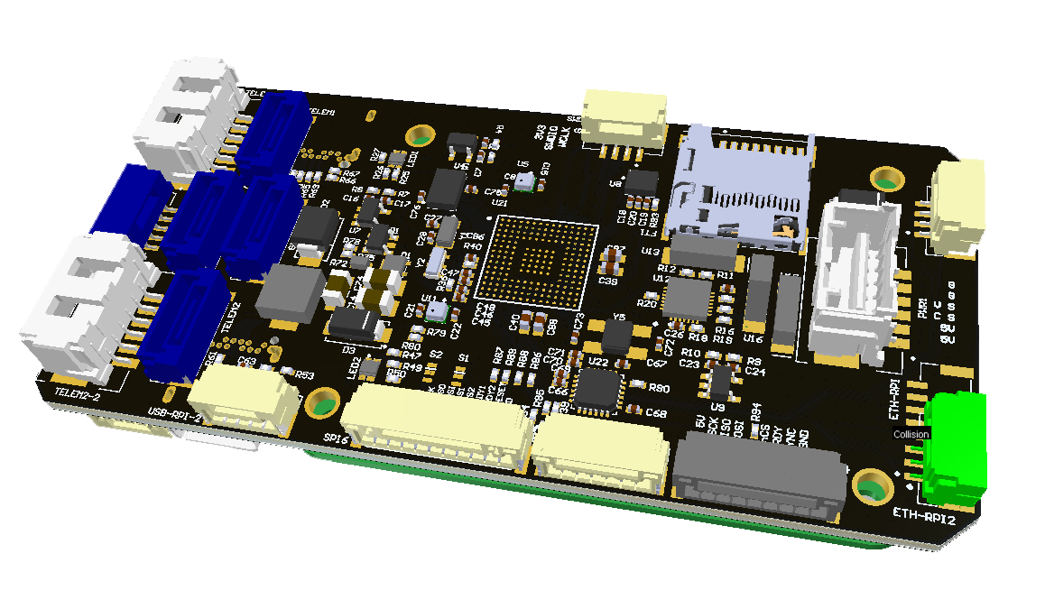
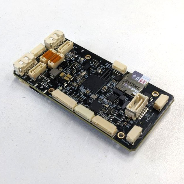
# Autopilot FMUv6X
It is based on the Pixhawk® Autopilot FMUv6X Standard (opens new window), Autopilot Bus Standard (opens new window), and Connector Standard (opens new window).
Equipped with a high performance H7 Processor, modular design, triple redundancy, temperature-controlled IMU board, isolated sensor domains, delivering incredible performance, reliability, and flexibility.
 |  |
# Key Design Points
- High performance STM32H753 Processor
- Modular flight controller: separated IMU, FMU, and Base system connected by a 100-pin & a 50-pin Pixhawk Autopilot Bus connector.
- Redundancy: 3x IMU sensors & 2x Barometer sensors on separate buses
- Triple redundancy domains: Completely isolated sensor domains with separate buses and separate power control
- Newly designed vibration isolation system to filter out high frequency vibration and reduce noise to ensure accurate readings
- Ethernet interface for high-speed mission computer integration
# Processors & Sensors
- FMU Processor: STM32H753
- 32 Bit Arm Cortex-M7, 480MHz, 2MB flash memory, 1MB RAM
- IO Processor: STM32F100
- 32 Bit Arm Cortex-M3, 24MHz, 8KB SRAM
- On-board sensors
- Accel/Gyro: ICM-20649 or BMI088
- Accel/Gyro: ICM-42688-P
- Accel/Gyro: ICM-42670-P
- Mag: BMM150
- Barometer: 2x BMP388
# Electrical data
- Voltage Ratings:
- Max input voltage: 36V
- USB Power Input: 4.75~5.25V
- Servo Rail Input: 0~36V
- Current Ratings:
- Telem1 output current limiter: 1.5A
- All other port combined output current limiter: 1.5A
# Mechanical data
- Dimensions
- Flight Controller Module: 38.8 x 31.8 x 14.6mm
- Standard Baseboard: 52.4 x 103.4 x 16.7mm
- Mini Baseboard: 43.4 x 72.8 x 14.2 mm
- Weight
- Flight Controller Module: 23g
- Standard Baseboard: 51g
- Mini Baseboard: 26.5g
3D model can be downloaded on GrabCAD (opens new window) (opens new window).

# Interfaces
16- PWM servo outputs
R/C input for Spektrum / DSM
Dedicated R/C input for PPM and S.Bus input
Dedicated analog / PWM RSSI input and S.Bus output
4 general purpose serial ports
- 3 with full flow control
- 1 with separate 1.5A current limit (Telem1)
- 1 with I2C and additional GPIO line for external NFC reader
2 GPS ports
- 1 full GPS plus Safety Switch Port
- 1 basic GPS port
1 I2C port
1 Ethernet port
- Transformerless Applications
- 100Mbps
1 SPI bus
- 2 chip select lines
- 2 data-ready lines
- 1 SPI SYNC line
- 1 SPI reset line
2 CAN Buses for CAN peripheral
- CAN Bus has individual silent controls or ESC RX-MUX control
2 Power input ports with SMBus
- 1 AD & IO port
- 2 additional analog input
- 1 PWM/Capture input
- 2 Dedicated debug and GPIO lines
Other Characteristics:
- Operating & storage temperature: -40 ~ 85°c
# Connectors
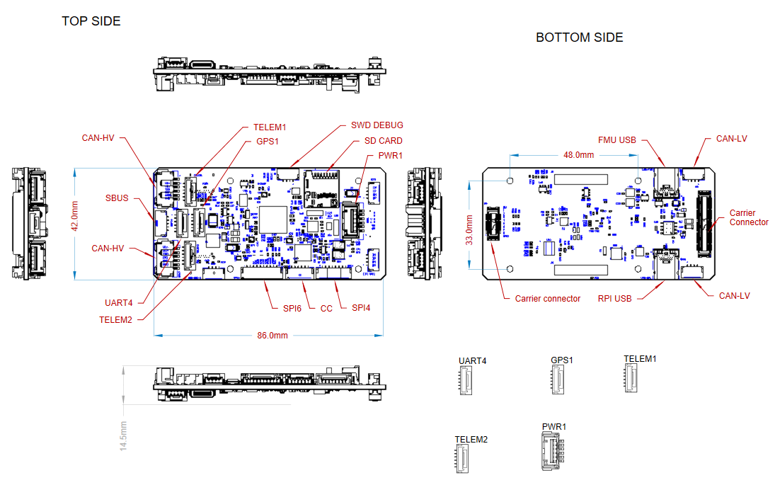
| № | Connector | Description |
|---|---|---|
| 1 | CAN-HV (1,2) | High Voltage CAN bus, typically for communication with peripherals that operate at higher voltage levels. |
| 2 | CAN-LV (1,2) | Low Voltage CAN bus, typically for communication with peripherals that operate at lower voltage levels. |
| 3 | FMU-USB | USB interface for connecting the Flight Management Unit (FMU) to a computer for programming or debugging. |
| 4 | TELEM1, TELEM2, UART4, GPS1 | Telemetry ports for communication with ground control stations or peripherals. |
| 5 | SWD-DEBUG | Serial Wire Debug interface for programming and debugging the microcontroller. |
| 6 | PWR1 | Power input for the system, typically used for connecting a battery or other power sources over 5v |
| 7 | SD CARD | SD card slot for storage, typically used for logging data or storing software. |
| 8 | SPI6 | Serial Peripheral Interface (SPI) port for high-speed communication with sensors or peripherals. |
| 9 | SPI4 | Another SPI interface, usually used for additional sensor or peripheral connections. |
| 10 | CC | Carrier Connector, typically for connecting the main processing board to the carrier board. |
| 11 | Carrier connector (2) | Additional carrier connector for expanding or connecting other peripherals to the carrier board. |
| 12 | RPI connector (2) | Raspberry Pi-compatible connector for attaching a Raspberry Pi or similar device. |
| 13 | RPI-USB | USB interface for connecting a Raspberry Pi or other devices to the system. |
TIP
ETH ports is not mentioned because of this function is under development.
# Serial Port Mapping
| UART | Device | Port |
|---|---|---|
| USART1 | /dev/ttyS0 | GPS |
| USART2 | /dev/ttyS1 | TELEM3 |
| USART3 | /dev/ttyS2 | Debug Console |
| UART4 | /dev/ttyS3 | UART4 & I2C |
| UART5 | /dev/ttyS4 | TELEM2 |
| USART6 | /dev/ttyS5 | PX4IO/RC |
| UART7 | /dev/ttyS6 | TELEM1 |
| UART8 | /dev/ttyS7 | GPS2 |
# Voltage Ratings
Pixhawk 6X can be triple-redundant on the power supply if three power sources are supplied. The three power rails are: POWER1, POWER2 and USB. The POWER1 & POWER2 ports on the Pixhawk 6X uses the 6 circuit 2.00mm Pitch CLIK-Mate Wire-to-Board PCB Receptacle (opens new window).
Normal Operation Maximum Ratings
Under these conditions all power sources will be used in this order to power the system:
- POWER1 and POWER2 inputs (4.9V to 5.5V)
- USB input (4.75V to 5.25V)
Absolute Maximum Ratings
Under these conditions the system will not draw any power (will not be operational), but will remain intact.
- POWER1 and POWER2 inputs (operational range 4.1V to 5.7V, 0V to 10V undamaged)
- USB input (operational range 4.1V to 5.7V, 0V to 6V undamaged)
- Servo input: VDD_SERVO pin of FMU PWM OUT and I/O PWM OUT (0V to 42V undamaged)
Voltage monitoring
# Building Firmware
For correct rotations of sensors and enabling exact sesors that used in our solution the file https://github.com/PX4/PX4-Autopilot/blob/main/boards/px4/fmu-v6x/init/rc.board_sensors should be modified:
# Magnetometers
# External compass on GPS1/I2C1 (the 3rd external bus): standard Holybro Pixhawk 4 or CUAV V5 GPS/compass puck (with lights, safety button, and buzzer)
ist8310 -X -R 4 start
rm3100 -I -R 1 start

# IMUs
# Internal SPI bus ICM42688p
icm42688p -R 4 -s start
# Internal SPI bus ICM20649
icm20649 -s -R 12 start
bmi088 -A -R 0 -s start
bmi088 -G -R 0 -s start


# Possible internal Baro
if param compare SENS_INT_BARO_EN 1
then
  icp201xx -I start
fi
TIP
Most users will not need to build this firmware! It is pre-built and automatically installed by QGroundControl when appropriate hardware is connected.
To build PX4 (opens new window) for this target:
make px4_fmu-v6x_default
# Debug Port
WARNING
CAN2 bus has issues and may not work at default firmware.
# Peripherals
# Supported Platforms / Airframes
Any multicopter / airplane / rover or boat that can be controlled with normal RC servos or Futaba S-Bus servos. The complete set of supported configurations can be seen in the Airframes Reference (opens new window).