# 2. Hardware
The electrical capabilities of the board are:
- Control of power supply of the starter EME35 or its analogues. For this purpose it is necessary to supply 6s-12s on-board power to the XT30 male connector (the supplied power must coincide with the power supplied to the CAN_HV_1 or CAN_HV_2 connectors), and the starter must be connected to the XT30 female connector. When the starter is started (based on the RawCommand input), the voltage of 8V is set on the XT30 female connector with a current limit of 33A.
WARNING
If the XT30 male connector is not connected, but CAN_HV_1 or CAN_HV_2 is connected and try to start the starter power supply, the board will fail.
Controlling the power supply of the ignition unit from the internal combustion engine (DLE 35RA or its analogues) and getting the engine revolutions. For this purpose it is necessary to connect revolutions to J3 pin1, pin2 power supply 5.3V pin 3 GND. Power is switched off/on by disconnecting/connecting pin3 ground (based on RawCommand input).
Control of gas and air flap of the internal combustion engine (DLE 35RA or its analogues).
To do this, connect servo-machines connected to air and gas flaps to the connectors AIR_PWM (J8), Throttle_PWM (J4). The power supply is 5.3V and a 2.6A fuse is installed on each connector
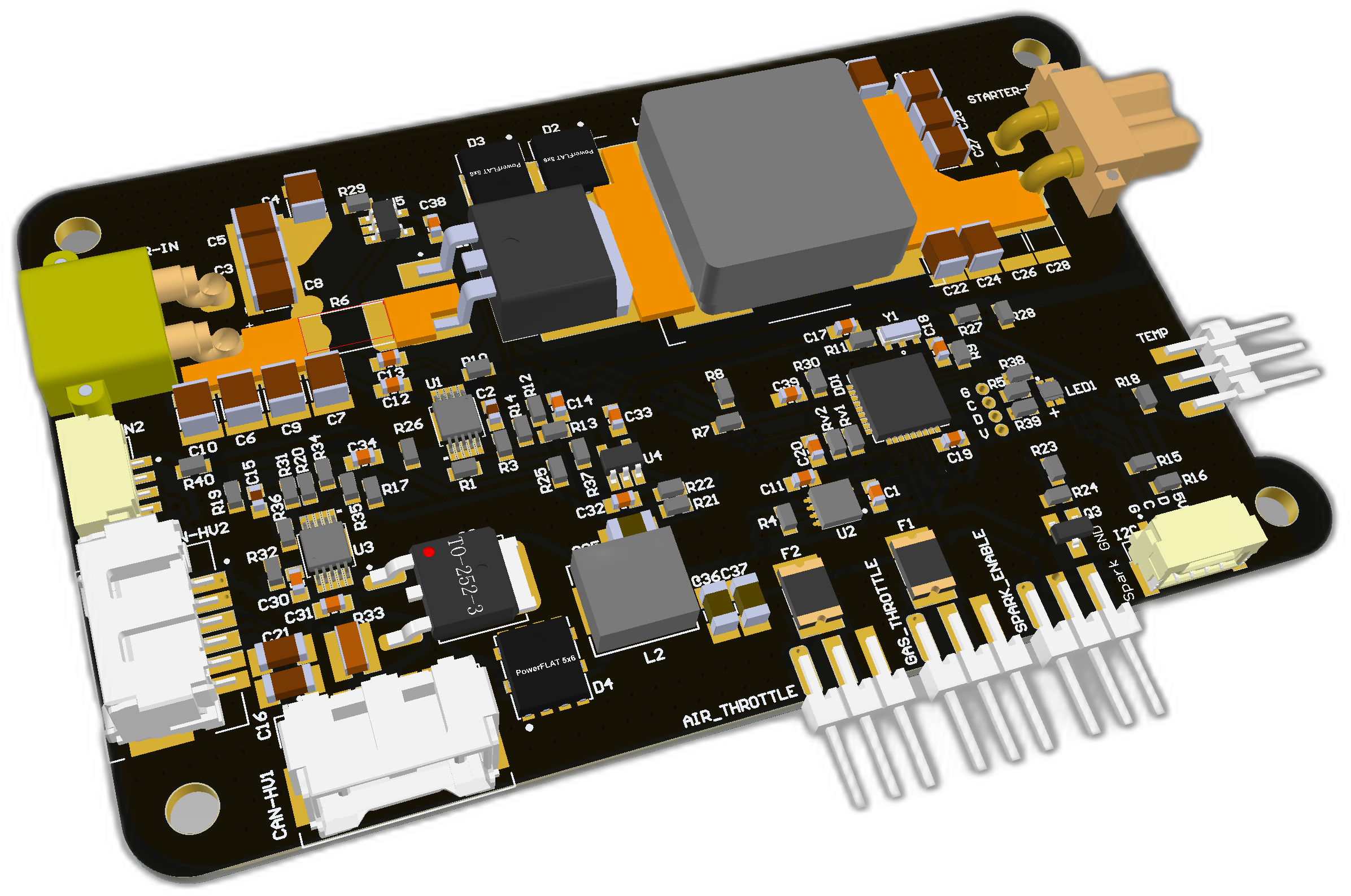 | 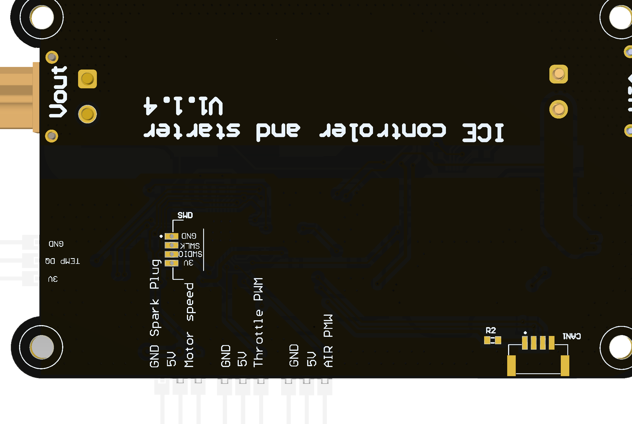 | 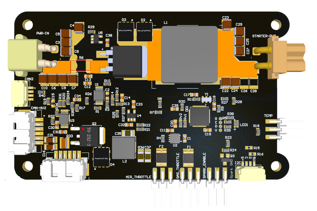 |
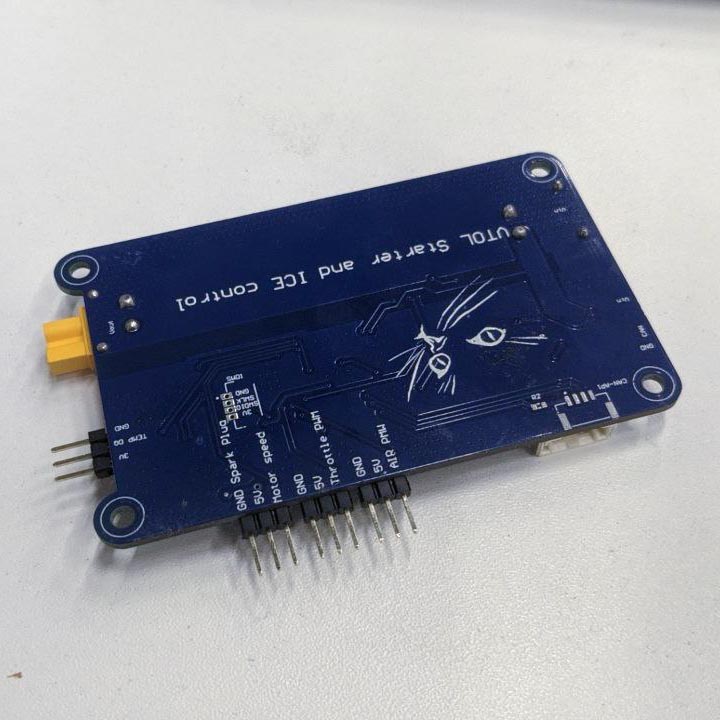 | 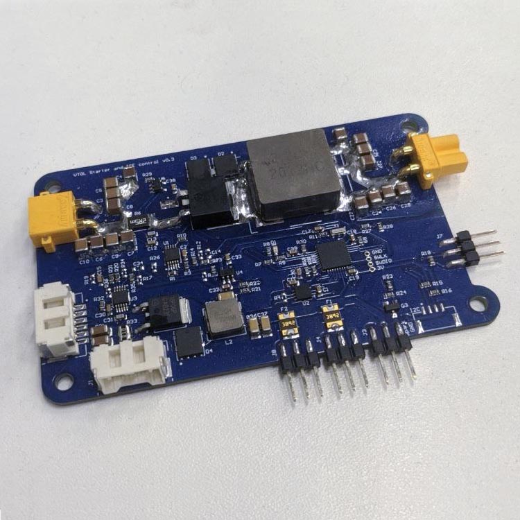 |
# 2.1 Features
- The board is designed for controlling the internal combustion engine (DLE 35RA or its analogues).
- PWM output for controlling the internal combustion engine gas flap (5.3V 2.5A).
- PWM output for controlling the internal combustion engine air damper (5.3V 2.5A).
- Output for controlling ignition unit and getting engine revolutions
- Output for controlling the electric starter (EME35 or its analogues)
- Output for thermostat (control of internal combustion engine temperature)
# 2.2 Wire
Schematic features. Schematic can be provided via issue.
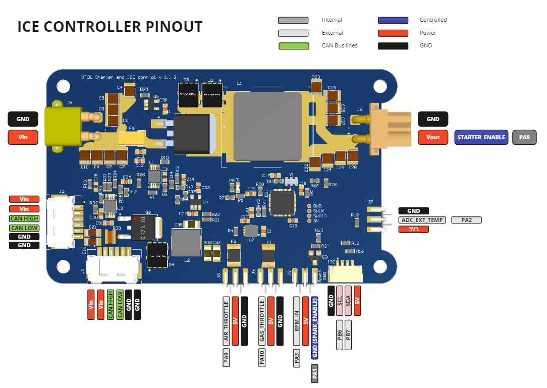
Connectors
The node has connectors which are described in the table below.
| № | Connector | Description |
|---|---|---|
| 1 | CAN-HV1, CAN-HV2 | Can be powered from 5.5 to 30 volts and connected to CAN. |
| 2 | SWD | STM32 firmware updating using programmer-sniffer. |
| 3 | AIR_THROTTLE, GAS_THROTTLE | The connector should be used to supply signal and power (below 1A) to the servo actuators controlling the air and gas flaps of the internal combustion engine |
| 4 | SPARK_ENABLE | The connector should be used to connect the ignition module. It controls the power supply to the ignition unit and receives the engine speed values |
| 5 | TEMP | The connector should be used to connect a thermistor |
| 6 | XT30 male | Input power supply for the DC-DC that powers the starter |
| 7 | XT30 female | Starter output power supply |
| 7 | I2C | Pay attention to GND and 5V. Not installed on the board by default. Backup connector able to connect to I2C bus power supply 5.3V current 1A |
| 7 | CAN1,CAN2 | It is not installed on the board by default. It should be used for connection to CAN bus, if it is necessary to supply power to this connector it is necessary to insert resistor R2. |
Pin configuration and functions
Input connectors:
| Pin N | CAN1,CNA2 | Pin N | CAN-HV1,CAN-HV2 | Pin N | SWD | Pin N | I2C |
|---|---|---|---|---|---|---|---|
| 1 | 5V | 1 | Vin | 1 | GND | 1 | GND |
| 2 | CAN_H | 2 | Vin | 2 | SWLK | 2 | SCL |
| 3 | CAN_L | 3 | CAN_H | 3 | SWDIO | 3 | SDA |
| 4 | GND | 4 | CAN_L | 4 | 3.3 | 4 | 5V |
| 5 | GND | 5 | |||||
| 6 | GND | 6 |
Output connectors:
| Pin N | GAS_THROTTLE,AIR_THROTTLE | Pin N | TEMP | Pin N | SPARK_ENABLE |
|---|---|---|---|---|---|
| 1 | throttle_PWM, AIR | 1 | 3V3 | 1 | motor speed |
| 2 | 5V (fused) | 2 | TEMP | 2 | 5V |
| 3 | GND | 3 | GND | 3 | GND (commutable) |
Here you can see all connections of MCU.
| MCU PIN | PIN Numer | NET Name | Description |
|---|---|---|---|
| PB1 | 16 | VERSION | VERSION |
| PA10 | 22 | throttle_PWM | GAS_THROTTLE |
| PA2 | 9 | TEMP_DQ | ADC_EXT_TEMP |
| PA14/JTCK/SWCLKI/O | 28 | SWLK | |
| PA13/JTMS/SWDIOI/O | 25 | SWDIO | |
| PA1 | 8 | spark_EN | SPARK_ENABLE |
| PB7 | 34 | SDA/A1 | |
| PB6 | 33 | SCL/A2 | |
| NRST | 4 | NRST | |
| PA8 | 20 | NetDD1_20 | STARTER_ENABLE |
| OSC_OUT/PD1 | 3 | NetDD1_3 | |
| OSC_IN/PD0 | 2 | NetDD1_2 | |
| PA3 | 10 | Motor_speed_IN | RPM_IN |
| PA4 | 11 | LED1 | INTERNAL_LED_1 |
| PA12 | 24 | CAN_TXD | |
| PA11 | 23 | CAN_RXD | |
| BOOT0 | 35 | BOOT0 | |
| PA9 | 21 | AIR | AIR_THROTTLE |
| PA5 | 12 | ADC_VIN | ADC_VIN |
| PB0 | 15 | ADC_CURRENT | ADC_CRNT |
| PA6 | 13 | ADC_16V | ADC_VOUT |
| PA7 | 14 | ADC_5V | ADC_5V |
# 2.3. Specifications
# Mechanical
Scheme is shown on the picture below. CAN model can be provided via email request or issue on github or downloaded on GrabCAD (opens new window).

| Width, mm | Length, mm | Height, mm | |
|---|---|---|---|
| Outline | 93.9 | 63.0 | 8.9 |
| PCB | 85.58 | 54.49 | 1.6 |
Total weight of device less than 50 g.
# Absolute Maximum Ratings
| Parameter | MIN | MAX | UNIT |
|---|---|---|---|
| Vin (HV) | 25 | 55* | V |
| V (LV) | 4.5 | 5.5 | V |
| I max | 1.0 | A | |
| I max | 1.0 | A | |
| Operating temperature |
*Noted Voltage should be delivered only with current limitation under 2.5 Amp.
WARNING
The input voltage must be connected via a special PMU board or current should be limited by any other solution to reach maximum input voltage
# Recommended operating conditions
| Parameter | Value | UNIT | Description |
|---|---|---|---|
| Vin (HV) | 30 | V | CAN HV |
| V (LV) | 5 | V | CAN LV |
| I max @ 41 V | 9 | mA | Board only |
| I max @ 41 V | A | Starter enabled | |
| I max @ 41 V | A | Starter with DLE-35RA as payload | |
| I max @ 41 V | A | Servos as a payload |
# ESD ratings
| Description | Value | UNIT |
|---|---|---|
| Human-body model (HBM) | 2000 | V |
| Charged-device model (CDM) | 500 | V |
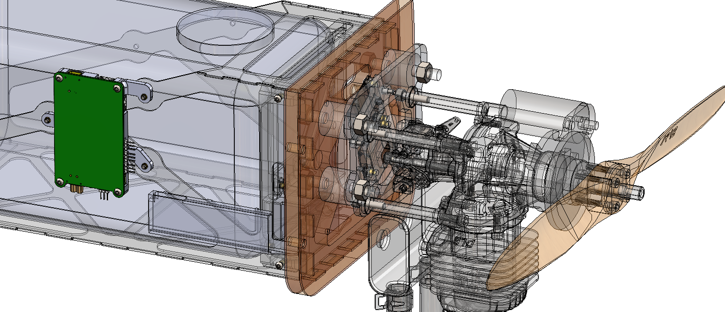
# 2.4. Integration
Recommended mechanical mounting
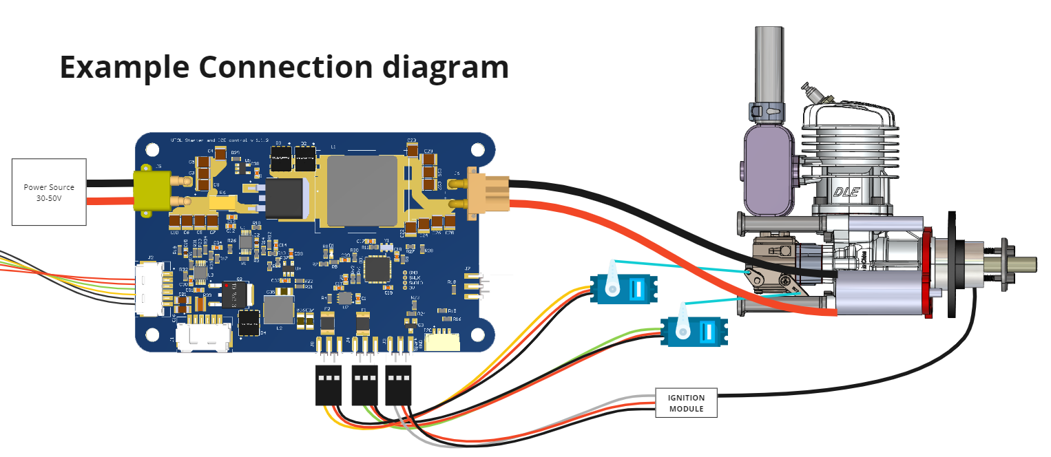
Connection example diagram
# 2.5. Power Supply Recommendations
Device is designed to operate from an input voltage supply range between 4.5 V and 5.5 V over CAN2 or CAN3 connector, or 5.5 - 30 V from CAN1. This input supply must be able to withstand the maximum input current and maintain a stable voltage. The resistance of the input supply rail should be low enough that an input current transient does not cause a high enough drop that can cause a false UVLO fault triggering and system reset. The amount of bulk capacitance is not critical, but a 47-μF or 100-μF electrolytic capacitor is a typical choice.
# 2.6. Revision history
| View | Version | Description |
|---|---|---|
 | v1.1.4 18.05.2024 | Latest version of the board Some other additional info |
| v1.1.3 | 28.06.2022 |