# 3. DroneCAN interface
This page is about DroneCAN software related details such as interface, supported features, parameters, configuration and usage example and version history.
This section refers to the latest released version of the software.
# 3.1. DroneCAN interface
This node interacts with the following messages:
| № | Type | Message | Meaning |
|---|---|---|---|
| 1 | sub | esc.RawCommand (opens new window) | Setpoint from PX4 [-8192, 8191]. It controls gas and air throttle, spark ignition and starter: - Negative or zero values are interpreted as a disarmed state where everything is disabled. - Setpoint == 1 enables spark ignition, but doesn't try to enable the starter motor - Setpoint >=2 tries to start the engine with a starter motor |
| 2 | sub | actuator.ArrayCommand (opens new window) | Air throttle open position. This is an optional command that allows you to adjust the open air throttle servo position in real time. |
| 3 | pub | ice.reciprocating.Status (opens new window) | Feedback from the ICE: RPM, internal node state, temperature and many other fields. |
Besides required and highly recommended functions such as NodeStatus and GetNodeInfo this node also supports the following application-level functions:
| № | type | message |
|---|---|---|
| 1 | RPC-service | uavcan.protocol.param (opens new window) |
| 2 | RPC-service | uavcan.protocol.RestartNode (opens new window) |
| 3 | RPC-service | uavcan.protocol.GetTransportStats (opens new window) |
# 3.2. DroneCAN parameters
The node has the following parameters:
| № | Register name | Description |
|---|---|---|
| 1 | uavcan.node.id | Defines a node-ID. Allowed values [0,127]. Default value is 42. DNA is not supported, so the node must have a valid ID. |
| 2 | air.cmd | Setpoint source - 0 means es.RawCommand (not supported) - 1 means actuator.ArrayCommand (by default). |
| 3 | air.ch | Index of setpoint channel. [-1; 255]. -1 means disabled |
| 4 | air.opening_duration_ms | Duration of opening the air servo |
| 5 | air.min_closed_initial | PWM duration when air throttle is closed (1500 us by default) |
| 6 | air.max_def_open_goal | PWM duration when air throttle is fully open (1500 us by default) |
| 7 | air.input_rc_min | Min value of input (for RawCommand typically is 1000, for ArrayCommand is -1.0 or 0.0 or 1000.0) |
| 8 | air.input_rc_max | Min value of input (for RawCommand typically is 2000, for ArrayCommand is +1.0 or 1.0 or 1000.0) |
| 9 | throttle.cmd | 0 means RawCommand, 1 means ArrayCommand. |
| 10 | throttle.ch | Index of setpoint channel. [-1; 255]. -1 means disabled |
| 11 | throttle.starter.period_on_ms | |
| 12 | throttle.starter.period_off_ms | |
| 13 | throttle.gas.min_def | PWM duration when throttle is 0 (RawCommand is 0 or Command is -1.0) |
| 14 | throttle.gas.max | PWM duration when setpoint is max (RawCommand is 8191 or Command is 1.0) |
| 15 | system.name | Defines custom node name. If empty, the node will use the default name. |
The detailed description of some of these parameters is shown in the chapters below.
# 3.3. Configuration / Engineering Testing
TIP
We strongly recommend that you perform engineering testing prior to installation on a real vehicle, especially if you are using the node for the first time. Testing includes configuring and using the node on a test bench under controlled conditions.
Hardware requirements:
- RL ICE node,
- USB-CAN Adapter (CAN-sniffer),
- 5V servo without load (2 servos are even better)
- Multimeter
Software requirements:
gui_tool. Use dronecan/gui_tool (opens new window) on Linux and OpenCyphal-Garage/gui_tool (opens new window) on Windows.
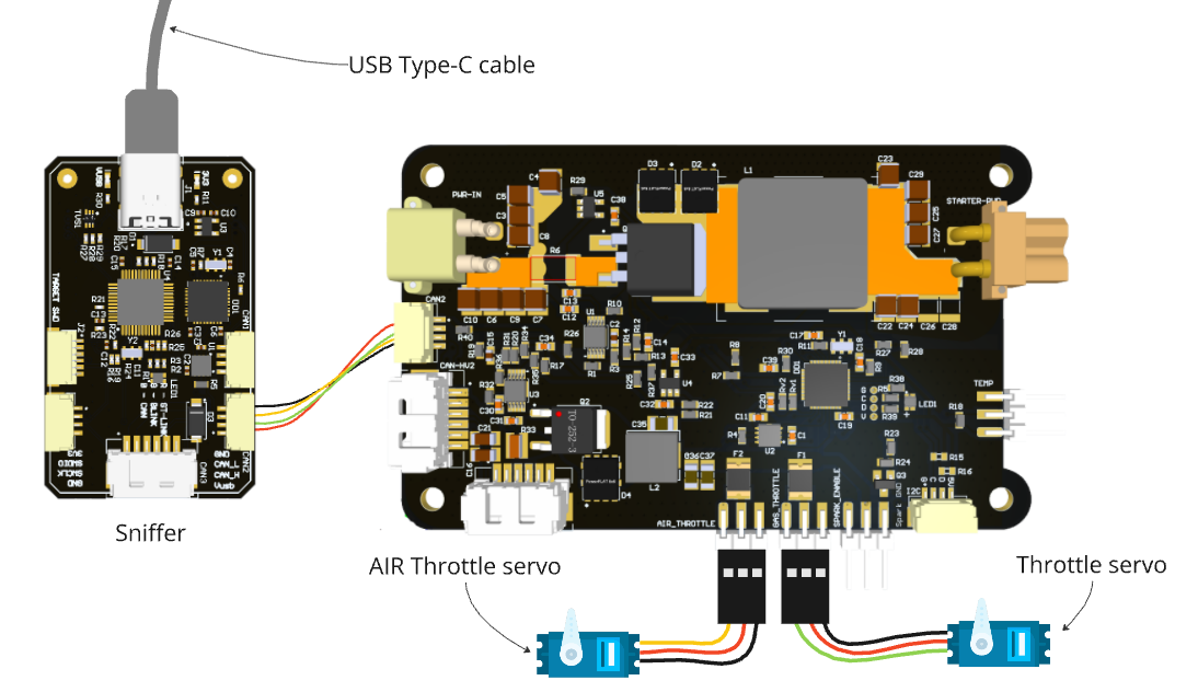
Step 1. Connect the node properly to a sniffer.
The simplest connection scheme just for bench testing and configuration is shown below.
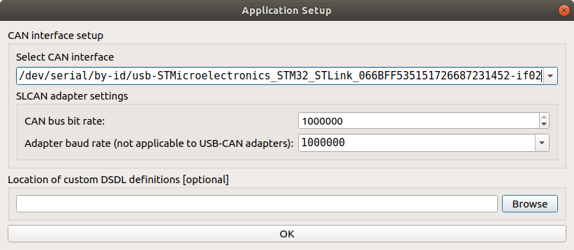
Step 2. Observe the node with gui_tool and set baudrate to 1000000
Step 2.1. Open gui_tool and set baudrate to 1000000
Step 2.2. Set the Local node ID. The node name appear in the Online nodes table
Apply the Local Node ID by clicking the button in the corresponding field at the top.
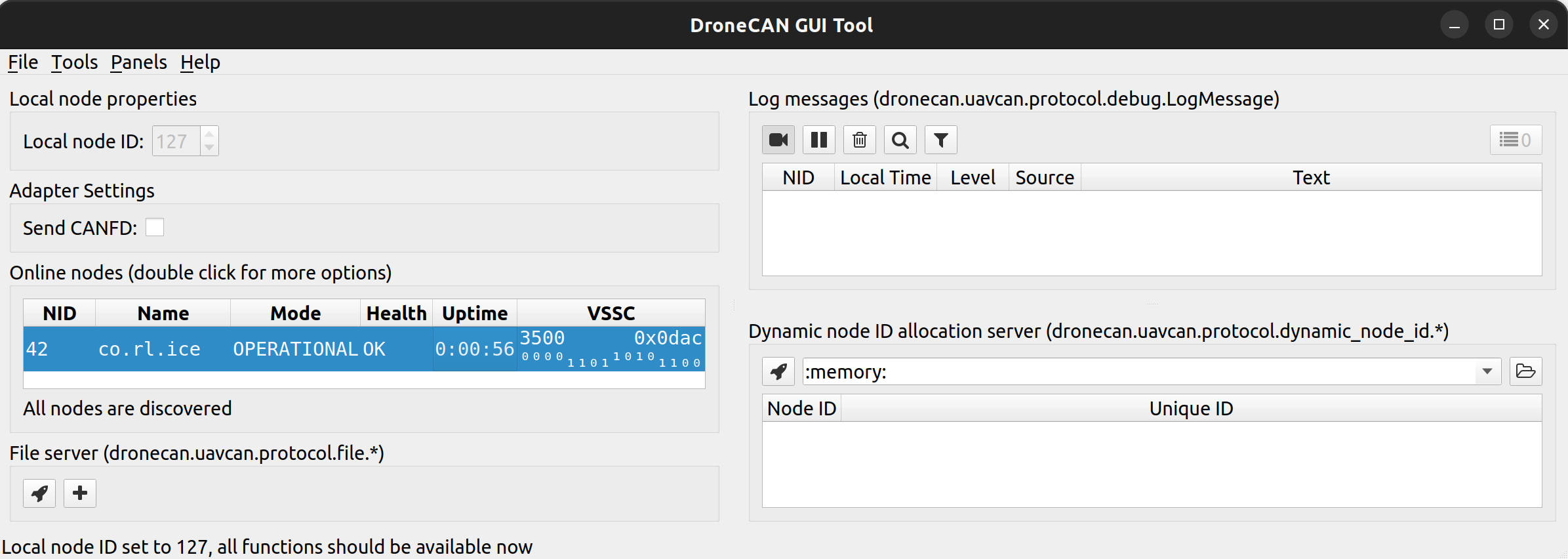
The node name is co.rl.ice. The default ID is 42. VSSC can be any value.
Step 2.3. Double click on the node name to get mode details
You can quickly press 2 times on the node in Online nodes list. A Node Properties window should appear. Press Fetch All button to obtain all the parameters.
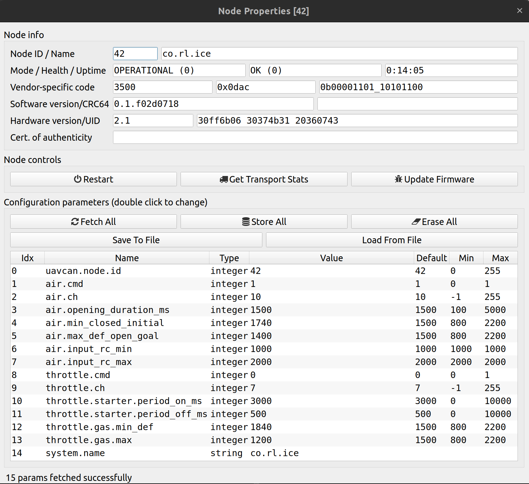
You should be able to see additional information such as node name, software version, UID, etc.
The node should respond with the software version that suits you (probably it should be the latest available stable version).
Step 2.4. Open Tools->Subscriber to get feedback
In the main gui_tool window press Tools->Subscriber to open a Subscriber window. Find uavcan.equipment.ice.reciprocating.Status and then press Enter or click on the Begin Subscription button.
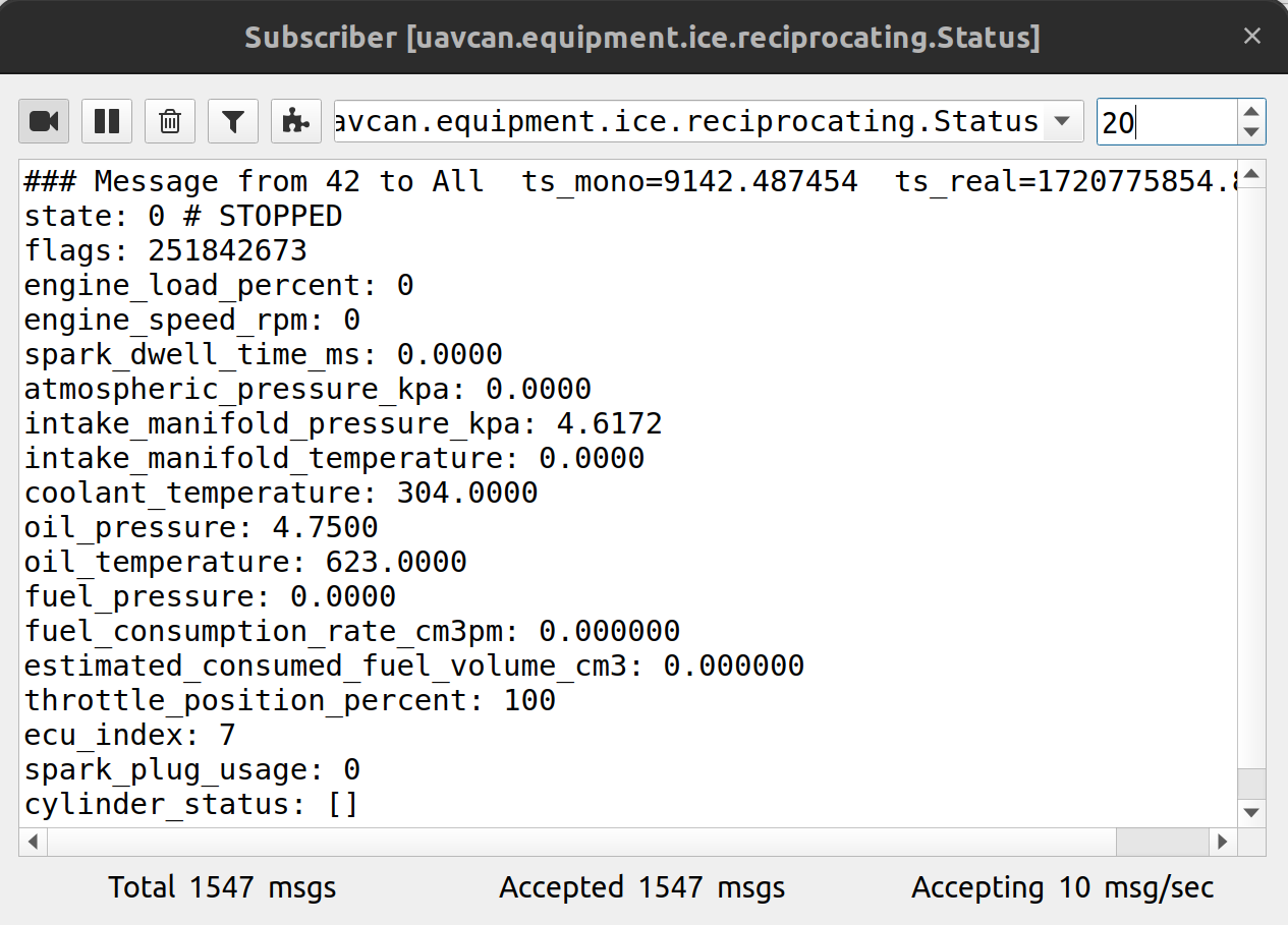
This is the main feedback from the node.
TIP
The ice.reciprocating.Status (opens new window) message was probably created for a very specific ICE application. The message has many fields we don't need, and it doesn't have all the fields the node can provide. But this is the best message DroneCAN can provide for our application. Since PX4 currently does nothing with this message, except just log the topic to the SD-card, let's fill these fields with something useful.
The table of meaning the message fields:
| Original field name | Actual meaning | |
|---|---|---|
| uint6 | ecu_index | Gas throttle channel number: 0 - 31 |
| uint2 | state | ICE node state: 0 - STOPPED 1 - RUNNING 2 - WAITING or FINISHER 3 - FAULT |
| uint17 | engine_speed_rpm | Filtered RPM, 0 - 12000 |
| float16 | atmospheric_pressure_kpa | Raw RPM, just for logging, 0 - 12000 |
| uint7 | engine_load_percent | Gas throttle, 0 - 100% |
| uint7 | throttle_position_percent | Air throttle, 0 - 100% |
| float16 | oil_temperature | External temperature, Kelvin |
| float16 | coolant_temperature | Internal (stm32) temperature, Kelvin |
| uint3 | spark_plug_usage | Spark plag state: 0 - Disabled 1 - Enabled |
| float32 | estimated_consumed_fuel_volume_cm3 | Spark ignition enabled time 0 - ignition disabled [1; +inf] - milliseconds from start |
| float16 | intake_manifold_temperature | current |
| float16 | intake_manifold_pressure_kpa | voltage 5v |
| float16 | oil_pressure | voltage vin |
| float16 | fuel_pressure | voltage vout |
| float16 | spark_dwell_time_ms | - |
| float32 | fuel_consumption_rate_cm3pm | - |
| uint30 | flags | Firmware git hash |
Check that these fields meets your expectation.
Step 3. Configure the node in relation to your application.
1. Set uavcan.node.id in relation to your application. The node ID should be unique within the CAN network to avoid ID collisions. For testing purpose, you can keep the default ID=42.
2. Configure air throttle air.* parameters:
air.cmdshould be 1. It means that the node will useactuator.ArrayCommandas setpoint. Other setpoint types are not supported at the moment.air.chshould be configured in relation to your application. For testing purposes, you can just set-1to disable it. This feature is useful for long-term usage with different environment conditions because it allows to adjust an open air throttle position in real time withactuator.ArrayCommand, but you always can do it with the parameters.air.opening_duration_ms. Keep 1500 ms, you can ajust it later.air.min_closed_initialandair.max_def_open_goalparameters define the PWM range to control an air throttle.air.input_rc_minandair.input_rc_max. Keep the default values You can ajust them later if you need.
3. Configure basic throttle.* parameters:
throttle.cmdshould be 0. It means that the node will useesc.RawCommandas setpoint. Other setpoint types are not supported at the moment.throttle.chshould be configured in relation to your airframe. By default it is7because it suits a specific PX4 airframe, so you probably want to change it. For testing purposes you can keep the default value
4. Configure throttle.starter.* parameters. period_on_ms and period_off_ms define the duration of attempt to initiate the combustion process. During the first period, the starter motor is enabled, during the second period the node checks if the engine fires and begins to run. For testing purposes, you can keep the default values 3000 ms and 500 ms. You can adjust it later.
5. Configure throttle.gas.* parameters. The parameters min_def and max define the PWM range to control a gas throttle.
The furher steps rely on that you have everyting by default except:
air.min_closed_initial = 1300air.max_def_open_goal = 1700throttle.gas.min_def = 1300throttle.gas.max = 1700
Step 4. Test gas throttle
Connect a 5V servo without load to the node via Throttle PWM, 5V and GND pins as show on the scheme below:
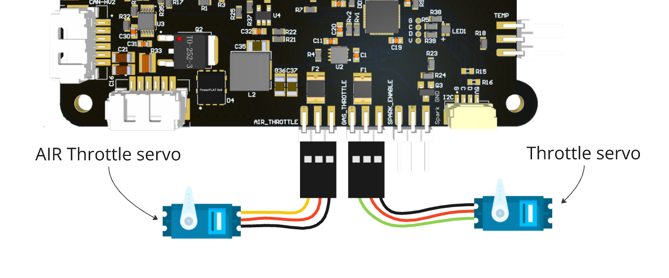
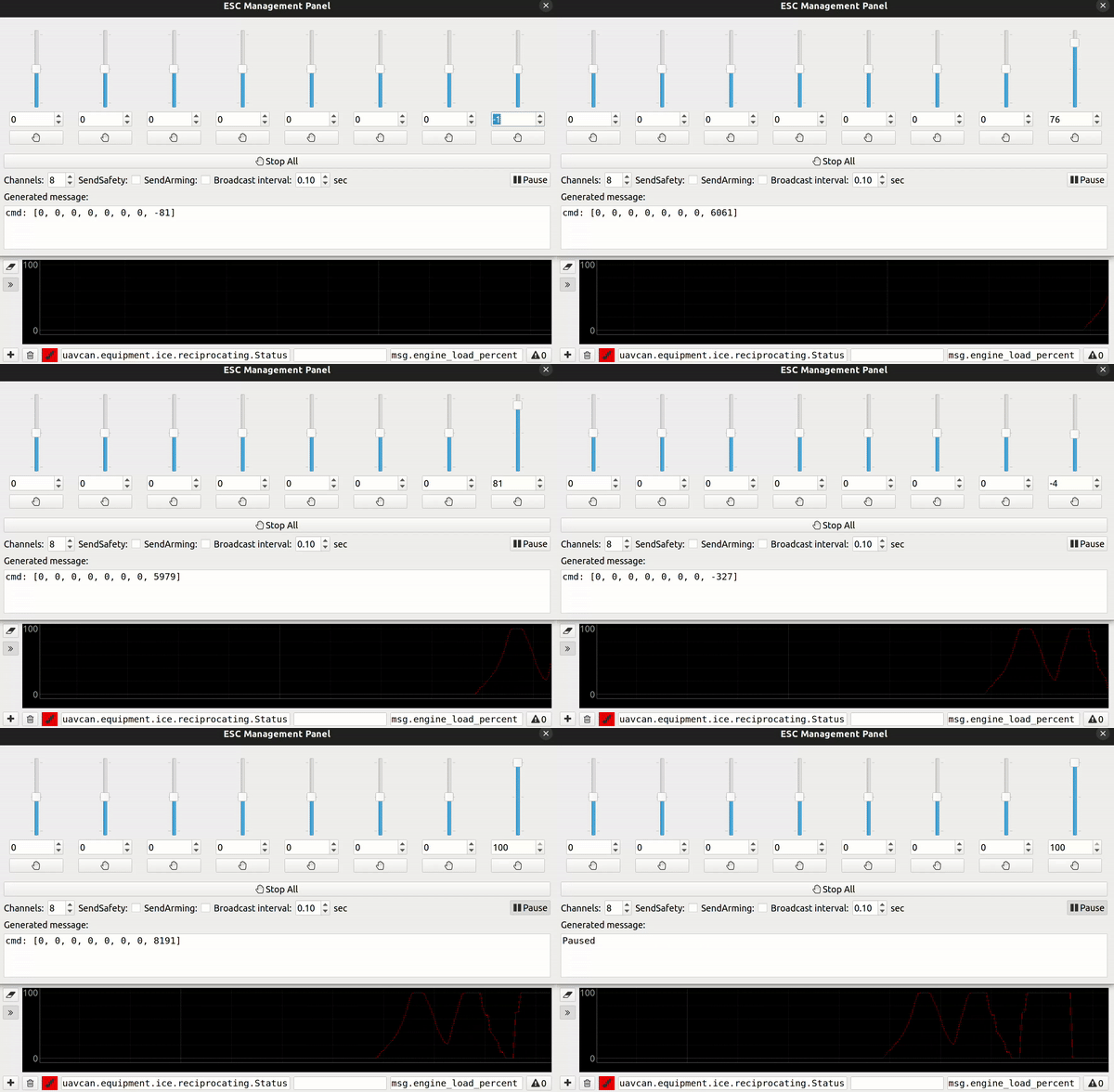
1. Open ESC Management Panel. Optionally create a plot with uavcan.equipment.ice.reciprocating.Status message and msg.engine_load_percent field.
2. Move the slider and verify that the servo rotates and the value on the plot changes as well.
3. Press Pause button. After 500 ms the node should move the servo to the default position. This is a safery feature. If the node loose the setpoint, it should turn everything off including moving the gas servo to the closed position.
Step 5. Test spark ignition control
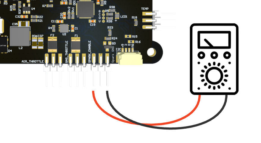
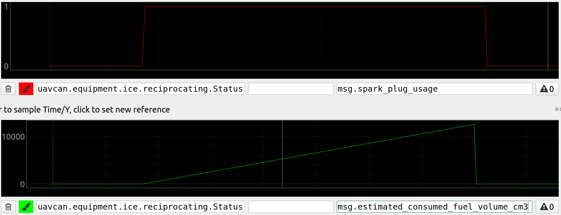
When the gas throttle setpoint (esc.RawCommand) is >= 0, the spark ignition is enabled, otherwise it is disabled.
You can create a plot here:
Step 6. Test starter motor control
When the gas throttle setpoint (esc.RawCommand) is >= 1, the node tries to fire up the engine and periodically enable starter.
On a bench you typically don't have a connected starter motor and Electronic Ignition Module, let's study this use case.
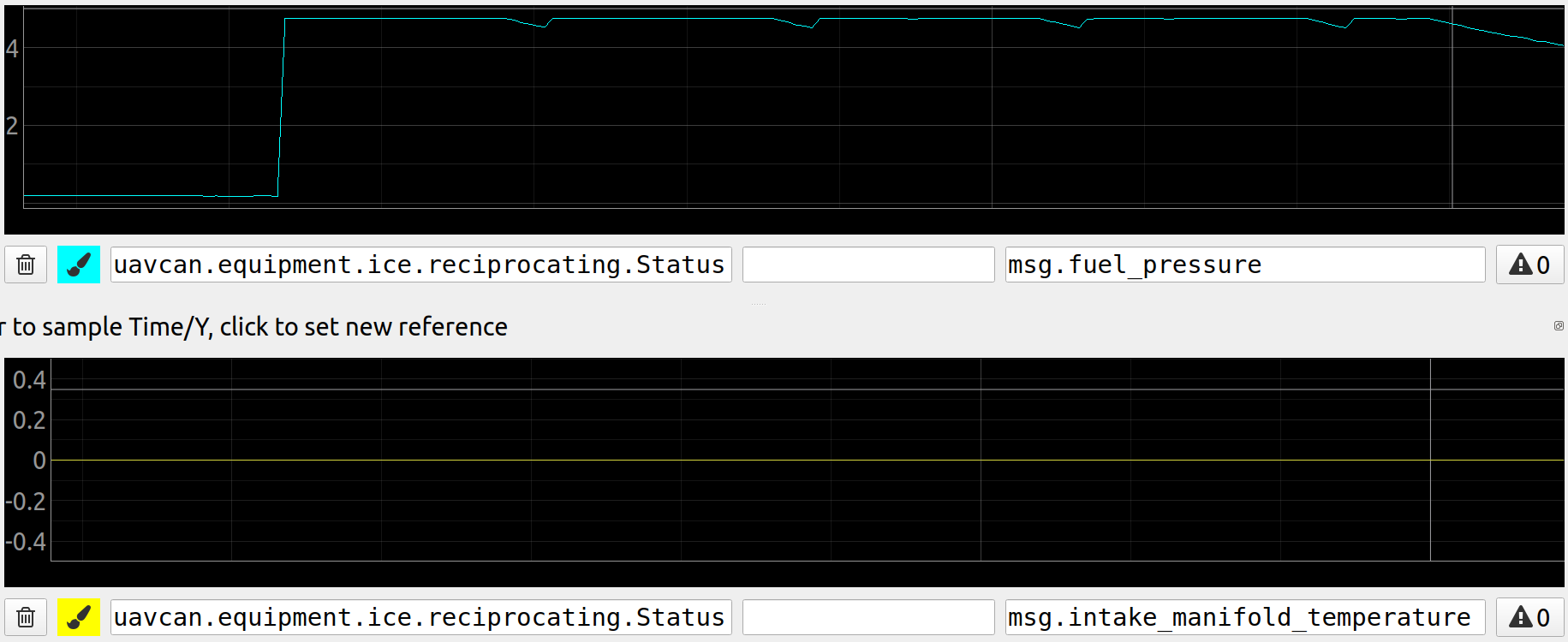
Let's try to fire up the engine 4 times and plot the following 4 fields:
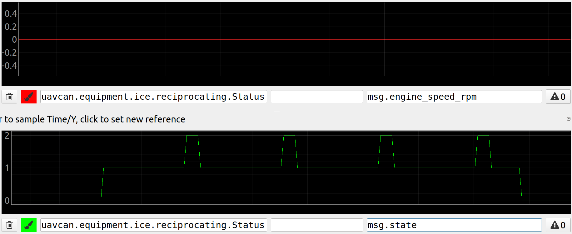
The first plot is about RPM feedback. Since it is not connected, it is 0 and all attemps to fire up were failed.
The second plot is about internal node state: 0 - stopped, 1 -running, 2 - waiting or finished. By default, the node enables starter for 3000 ms and wait for 500 ms. The whole period is 3500 ms.
The third plot is Vout voltage. Since a starter motor is not connected, it is not enough time for voltage to go down beetween attempts.
The fourth plot is about current. Since a starter motor is not connected, it is just 0 Ampers.
A real use case is considered later.
Step 7. Test air throttle control
Connect a servo to AIR PWM, 5V and GND pins as show on the scheme below:

Air throttle position depends on the node state.
Let's consider the similar use case as above: the starter and EIM are not connected, 4 attemtps to fire up the engine. We can plot the 2 fields:


The first plot is about internal node state.
The second plot is air throttle position.
Step 8. Test stm32 and external temperature
The message fields are:
- coolant_temperature - Internal (stm32) temperature, Kelvin
- oil_temperature - ICE temperature, Kelvin, need an external temperature sensor
TIP
Add a connection scheme for an external temperature sensor here!
Step 9. Test RPM measurement
The message fields are:
- engine_speed_rpm - Filtered RPM, 0 - 12000
- atmospheric_pressure_kpa - Raw RPM, just for logging
TIP
If you perform bench testing, there is a simple way to check RPM measurement feature. Since AIR PWM and Throttle PWM are PWM with 50 Hz frequency, you can connect it with Motor speed pin. If the RPM measurement is fine, the node should measure 3000 RPM.
# 3.4. PX4 integration
The following parameters are required to be configured:
- UAVCAN_ENABLE=3
- UAVCAN_SUB_ICE=1
It is recommended using PX4 at least v1.13.3 or newer and New Dynamic Mixing System (opens new window). Please, just follow the official Actuator Configuration and Testing (opens new window) docs.
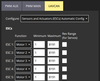
The ICE node expects you to use the default config for the ICE channel: Minimum value should 1 and Maximum value should be 8191.
Let's look at an example of a Generic Standard VTOL airframe in detail and explain how the ICE node works in different situations. Let's configure ESC 1-4 as quadcopter ESC and ESC 5 as ICE. The control surfaces (ailerons, elevators, rudders) are configured as Servos and they are out of scope of this example. Below there is an example of configuration where ESC 5 is ICE:
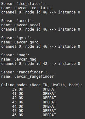
If the ICE node is succesfully connected to the autpilot, you should see the node when type uavcan status command in MAVLink console. An example of output could be:
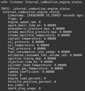
Type listener internal_combustion_engine_status to check the node feedback. An example output is:
If you see that the ice status message is published in UORB, you should be able to see it in MAVLink Inspector as well that is useful for debugging:
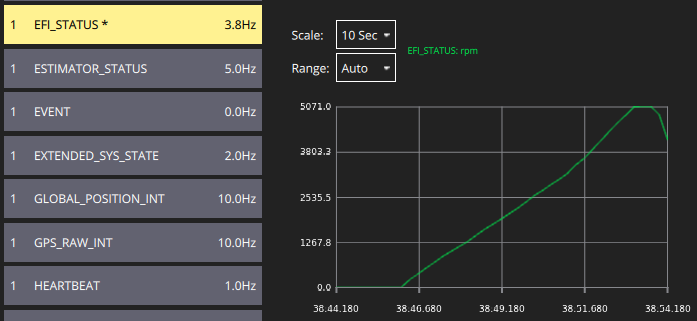
You can also move some fields of the EFI_STATUS message into a QGC panel:

Let's study how does ICE node works in details.
1. Initially the autopilot sends an empty esc.RawCommand command. ICE node ignores this command because it doesn't have a required channel. The node automatically disable everything if it doesn't receive the required channel for 500 ms.

2. In MR mode the autopilot sends commands to ESC1-4, but not for ESC5 yet. The command can be as shown below:

Since the message doesn't have a required for the ICE node channel, the node ignores this command as well.
3. In FW mode the autopilot turns off all quadcopter related motors and adds the 5th channel as shown below:

Now the ICE node is engaged: it controls the gas and air throttle servos, the starter motor and the spark ignition. The minimal command value is 1 and the maximum in 8191 as configured above.
4. When we go back to the MR mode, the autopilot sends command to MR related motors again, but this time it includes 0 value for the ICE node:

Zero setpoint forces the ICE node to turn off everything imideately.
5. After landing the PX4 sends the following command:

WARNING
Add info about the custom PX4 version...
# 3.5 Functional testing
TIP
We recommend testing the ICE node is a safe conditions before a real flight. Take care about the safety!
After the ICE node is configured, mounted on a vehicle and succesfully connected with PX4-autopilot, try the node on the ground.
On the video below the node was tested with ICE DLE 35RA and starter EME35 (by the way, this is the only recommended setup) with empty fuel tank without quadcopter motors. The pilot switched the vehicle into FW mode.
Click on the video:
1. Starter. We can see 3 clear attemps of the starter motor to fire up the engine. Here the attempt duration is 4000 ms and the delay is 1500 ms.
2. Air throttle. You can also see the air throttle servo moving beetween the closed and open positions.
3. Gas throttle. In the beginning you can also see a movement of the gas throttle servo. The throttle had a fixed position. You can rotate it to see the gas throttle actuatual changes.
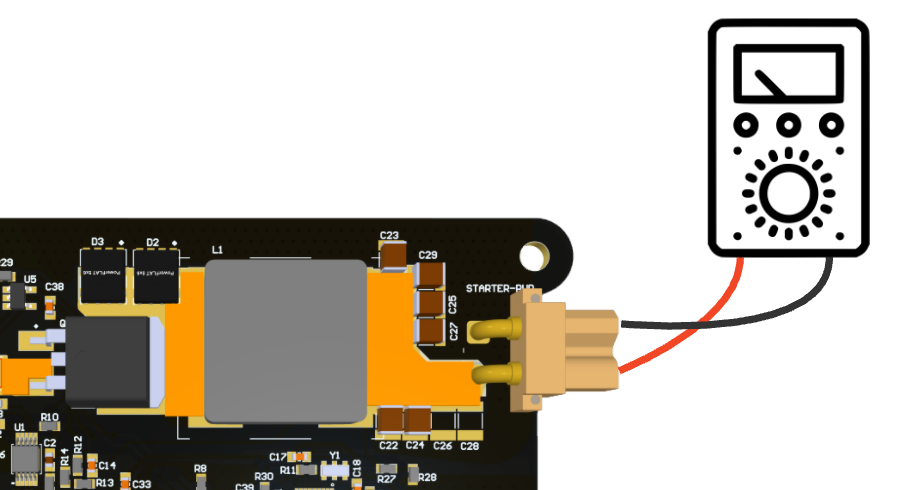
4. Spark ignition. Additionally, you can connect a multimeter to verify that the spark ignition is correctly controlled.
After this test the vehicle is ready for tests with fuel.
# 3.6 Real usage
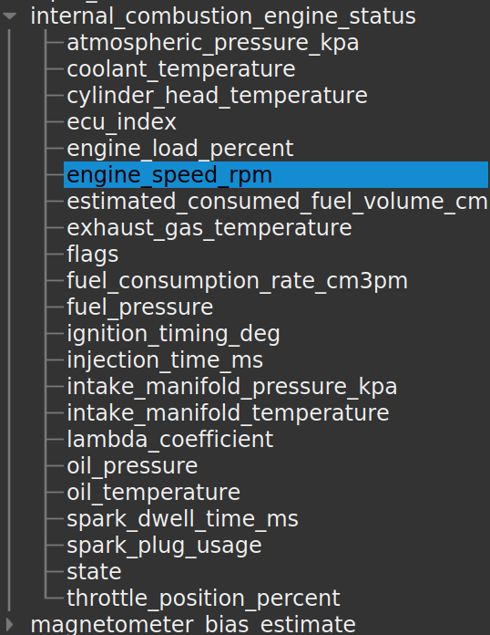
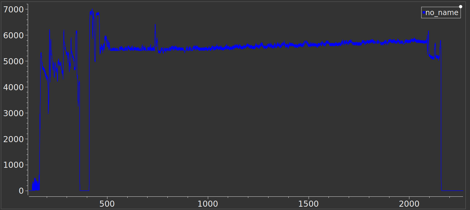
This node has been successfully tested on VTOL. Here is an example of RPM and esc.RawCommand values collected from one of the flight logs.
 |  |
# 3.7. Software versions
History of all releases and changes related to the node:
| Version | Date | Description |
|---|---|---|
| v0.4.3 9d466be (opens new window) | Jul 14, 2024 | First beta release |
| v0.3.4_98e6371 (opens new window) | Dec 27, 2021 | Alpha release |
| v0.3.2_8b0c6cf (opens new window) | Jun 10, 2021 | Alpha release |
| v0.3.0_7baa09b (opens new window) | Apr 5, 2021 | Alpha release |
← 2. Hardware 1. Wires →
