# Connector standard
This standard defines all hardware aspects of building a compatible device. It is based on DS-009 PX4 Standard (opens new window) and DRONECAN Hardware Design Recommendations (opens new window) and aims to be compatible with these technologies.
# 1. Related Standards
- DS-009 Pixhawk Connector Standard (opens new window)
- UAVCAN Hardware design recommendations (opens new window)
- DS-010 Pixhawk Autopilot Bus Standard (opens new window)
- DS-012 Pixhawk Autopilot v6X Standard (opens new window)
# 2. Connector Series
This standard is intended for in-vehicle, cross-PCB use. It uses the series that offers a latch lock mechanism with small size and a very competitive cost.
- MOLEX 502585-0670 (opens new window)
- JST SM04B-GHS-TB(LF)(SN)
- JST SM06B-GHS-TB(LF)(SN)
- 3PIN PWM connector B-2100S03P-A110
- AMASS XT30U-M, XT30U-F, XT30PW-M, XT30PW-F, XT60-M, XT60-F
- MCX coaxial 50 Ohm connector
- USB Type-C UJ31-CH-31N-SMT-TR
# 3. Vehicle cable harness and electrical design concept
This page explains how to reduce the possibility of vehicle failure due to poor electrical connections in the wiring harness.
# 3.1. Power lines
From a power supply standpoint, we suggest following 2 recommendations.
Recommendation 1. Use 6-pin connectors instead of 4-pin connectors
Let's represent a wire harness as a simple electrical circuit, as shown in the figure below.

Although DS-009 Pixhawk Connector Standard (opens new window) recommends using a 4 pin connector (JST SM04B-GHS-TB(LF)(SN)) where the only one wire is responsible for powering a peripheral device, our concept offers to use a 6 pin connector (MOLEX 502585-0670 (opens new window)) where at least two wires are responsible for the powering.
We can summarize the resistance of the the circuit as follows:
- For 4-pin JST GHR-04V-S connector (recommended in DS-009 Pixhawk Connector Standard (opens new window)) we have:
Rcircuit = Rcon * 4 + Rwire * 2 * length
- For 6-pin MOLEX 5025780600 connector we have (recommended in this standard):
Rcircuit = (Rcon * 4 + Rwire * 2 * length)/2
| Part | Name | Resistance |
|---|---|---|
| JST GHR-04V-S (opens new window) | Rcon | 50 mOhm contact resistance |
| MOLEX housing 5025780600 (opens new window) | Rcon | 20 mOhm |
| AWG#28 wire* | Rwire | 213 mOhm/m (opens new window) |
As it is written in DS-009 Pixhawk Connector Standard (opens new window) the power voltage is 5 volts @ 1 amp, so we can calculate the voltage drop from the power source to the device, in case of minimum interconnections inside the vehicle.
| Current | Length | Voltage drop |
|---|---|---|
| 0.1 A | 170 mm | 27 mV |
| 0.5 A | 170 mm | 126 mV |
| 1 A | 170 mm | 272 mV |
| 0.1 A | 500 mm | 41 mV |
| 0.5 A | 500 mm | 206 mV |
| 1 A | 500 mm | 413 mV |
In case of using MOLEX 6-pin cable the voltage drop decreases:
| Current | Length | Voltage drop |
|---|---|---|
| 0.1 A | 500 mm | 14 mV |
| 0.5 A | 500 mm | 73 mV |
| 1 A | 500 mm | 147 mV |
By using MOLEX 6-pin connector instead of JST 4-pin connector we have 2 advantages:
- MOLEX 6-pin connector increases the reliability of the power supply by redundancy, because the possibility of failure of 2 wires at the same time is less than that of 1 wire.
- MOLEX 6-wire allows the use of a more longer branch of the network.
Recommendation 2. Use an individual voltage regulators on each node
Let's take a look at the commonly used power up scheme.
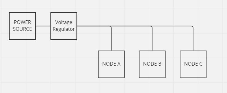
In this scheme, if the central Voltage Regulator fails due to an internal problem, all NODEs will lose power.
Now let's take a look at another approach described in the next schema.
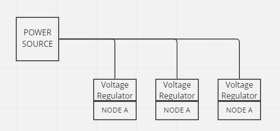
In the second scheme, if there is a problem inside the device, it will not cause the vehicle to abort.
It is recommended that each node have its own voltage regulator.
Summarizing:
Our approach has the following advantages:
- Backup power lines
- Length of the longest wire can be longer than 0.5 m
- Failure of a single NODE will not propagate to other nodes and will not result in vehicle termination.
# 3.2. Topology
It is highly recommended to provide two parallel connectors for each interface per device, so that the device can be connected to the bus without the need to use T-connectors. T-connectors should be avoided (opens new window) when possible because generally they add an extra point of failure, increase the stub length, weight, and often require more complex and expensive wiring harnesses.
It is better fo follow next recommendations for the bus topology design:
- Separate into horizontal and vertical buses. Then have a bridge between them.
- Use a SNAKE topology instead of T-shape.
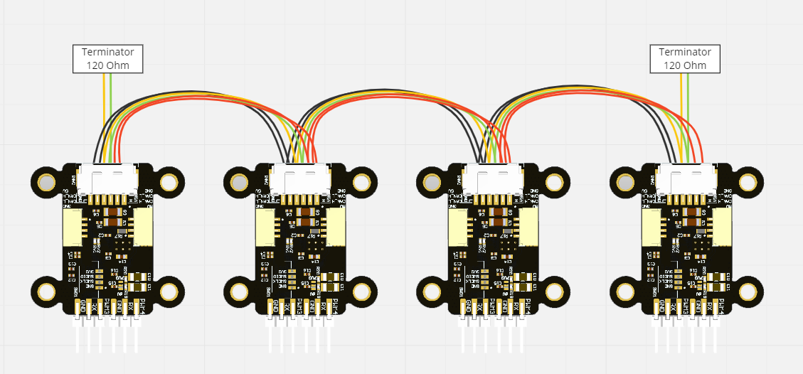
The figure below demonstrates a bus wired according to the above recommendation.

The next figure shows a bus where the devices are equipped with doubly redundant interfaces. The same principles apply to a triply-redundant bus as well.
Unfortunately sometimes it is necessary to use T-connectors or star topology on bus. In this case its better use bus splitter.
# 3.3. Reliability and Redundant interfaces
Mission critical and non-mission critical devices often need to co-exist on the same network. Non-mission critical devices are likely to be equipped with a non-redundant bus interface, which can create the situation where multiple devices with a different number of redundant interfaces need to be connected to the same network.
If multiple devices with a different number of interfaces need to co-exist on the same network, the following rules should be followed:
- Each available CAN bus (DroneCAN supports up to 3) is assigned a level of importance (primary or backup).
- All devices should be connected to the primary CAN bus.
- Only devices with redundant interfaces should be also connected to the backup bus/buses.
The figure below shows a doubly redundant CAN bus, but the same considerations apply to a triply redundant bus:
# 4. Connectors specification standard
# 4.1. CAN
Recommended CAN transceivers: TJA1042TK/3 (opens new window) or TJA1051TK3/118 (opens new window) or LTC2875 (opens new window). Ensure to twist the wires.
# Molex 6-pins Cable (SMX R)
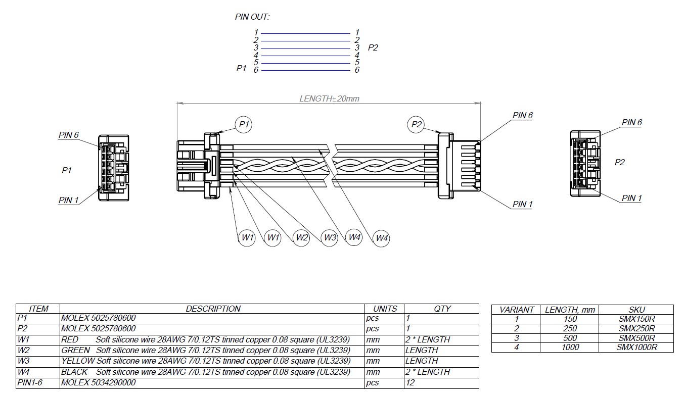
This pinout should be used for any CAN ports. In case of developing vehicle thet outline dimensions grater than 0.5 m its recomended to use self sufficient devices with voltage regulator on board. In this case port should be able to transfer needed power. Recommended connector is MOLEX 502585-0670 (opens new window) and it mates with MOLEX 6-pins cable (opens new window), and it can be assembled by you self using MOLEX housing 5025780600 (opens new window) and 6 pins 5025790000 (opens new window).
| Pin | Signal | Max voltage |
|---|---|---|
| 1 | Vin | 60 |
| 2 | Vin | 60 |
| 3 | CAN High | 60 |
| 4 | CAN Low | 60 |
| 5 | GND | GND |
| 6 | GND | GND |
# JST 4-pins cable (SJT R)
The Micro connector is intended for weight- and space-sensitive applications. It is a board-level connector, meaning that it can be installed on the PCB rather than on the panel.
The Micro connector is compatible with the Dronecode Autopilot Connector Standard. This connector type is recommended for small UAV and nanosatellites. It is also the recommended connector for attaching external panel-mounted connectors (such as the M8 or D-Sub types) to the PCB inside the enclosure.
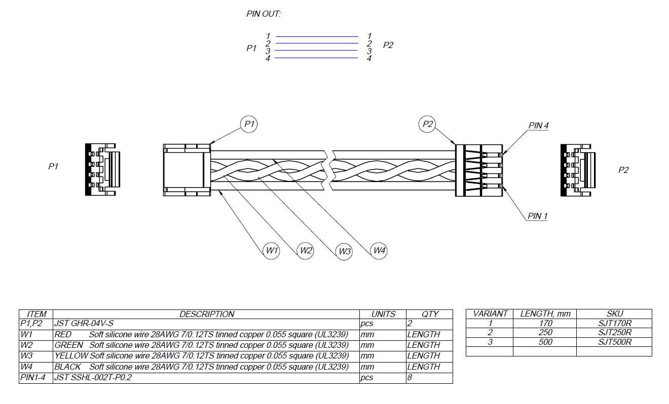
In case of using low power devices and small vehicle. And in the way of compatibility with PX4 standards its recommended to use 4 pin JST SM04B-GHS-TB(LF)(SN) connector that suits with JST 4-pins cable (opens new window). And can be assembled using next PN: JST GHR-04V-S (opens new window) and pin SSHL-002T-P0.2 (opens new window).
| Pin | Signal | Max. voltage |
|---|---|---|
| 1 | Vcc | 5.5V |
| 2 | CAN High | 3.3V |
| 3 | CAN Low | 3.3V |
| 4 | GND | GND |
Devices that deliver power to the bus are required to provide 5.0—5.5 V on the bus power line. The anticipated current draw is up to 1 A per connector.
Devices that are powered from the bus should expect 4.0—5.5 V on the bus power line. The maximum recommended current draw from the bus is 500 mA per device.
Advantages
- Extremely compact, low-profile. The PCB footprint is under 9✕5 millimeters.
- Secure positive lock ensures that the connection will not self-disconnect when exposed to vibrations.
- Low-cost, easy to stock.
Disadvantages
- Board-level connections only. No panel-mounted options available.
- No shielding available.
- Not suitable for safety-critical hardware.
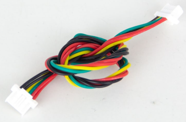
As alternative UCANPHY Micro patch cable (opens new window) can be used.
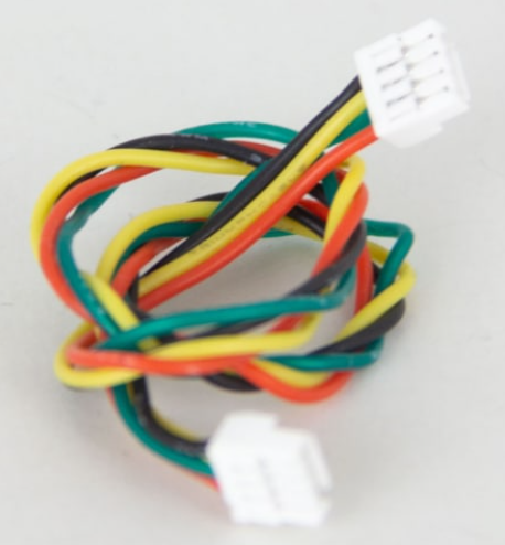
Photo of this type of wire presented below.
Mechanical drawing is presented here.
# 4.2. Telemetry Port
This pinout should be used for any serial port. Cables should be 1:1 to the master and TX / RX as well as CTS / RTS should be crossed on the master side (e.g. a autopilot would have its RX port on pin 3, TX port on pin 2, RTS on port 5 and CTS on port 4).
Devices that supports flow control should use 4 pin JST SM06B-GHS-TB(LF)(SN) connector.
| Pin | Signal | Max. voltage |
|---|---|---|
| 1 | Vcc | 5.5V |
| 2 | RXI | 3.3V |
| 3 | TXO | 3.3V |
| 4 | RTS | 3.3V |
| 5 | CTS | 3.3V |
| 6 | GND | GND |
Ports not supporting hardware flow control should use 4 pin JST SM04B-GHS-TB(LF)(SN) connector that suits with JST 4-pins cable (opens new window). And can be aseembled using next PN: JST GHR-04V-S (opens new window) and pin SSHL-002T-P0.2 (opens new window).
| Pin | Signal | Max. voltage |
|---|---|---|
| 1 | Vcc | 5.5V |
| 2 | RXI | 3.3V |
| 3 | TXO | 3.3V |
| 4 | GND | GND |
# 4.3. SBUS
Connector is compatible with JST 4-pins cable (SJT R).
Pinout is presented below.
| Pin | Signal | Max. voltage |
|---|---|---|
| 1 | Vcc | 5.5V |
| 2 | SBUS | 3.3V |
| 3 | RSSI | 3.3V |
| 4 | GND | GND |
# 4.4. I2C port
Connector is compatible with JST 4-pins cable (SJT R).
Pinout is presented below.
| Pin | Signal | Max. voltage |
|---|---|---|
| 1 | Vcc | 5.5V |
| 2 | SCL | 3.3V |
| 3 | SDA | 3.3V |
| 4 | GND | GND |
# 4.5. SPI port
Pinout is presented below.
| Pin | Signal | Max. voltage |
|---|---|---|
| 1 | Vcc | 5.5V |
| 2 | CLK | 3.3V |
| 3 | MISO | 3.3V |
| 4 | MOSI | 3.3V |
| 5 | SS1 | 3.3V |
| 6 | GND | GND |
# 5. Internal Debug Connectors
# 1. This standard
For STM32 firmware updating using programmer-sniffer it suggested to use same SJT170R cable with SWD-NEEDLE adapter.
Pinout is presented below.
| Pin | Signal | Max. voltage |
|---|---|---|
| 1 | 3.3V | 3.3V |
| 2 | SWDIO | 3.3V |
| 3 | SWCLK | 3.3V |
| 4 | GND | GND |
# 2. Other options
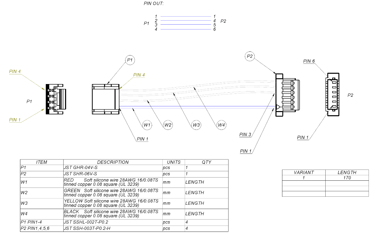
Its possible to update firmware using SWD-NEEDLE adapter and SJT170DB wire in case of usage Zubax probe (opens new window) debugger.
Pinout of connector with part number SM06B-SRSS-TB is presented below.
| Pin | Signal | Max. voltage |
|---|---|---|
| 1 | 3.3V | 3.3V |
| 2 | TXO | 3.3V |
| 3 | RXI | 3.3V |
| 4 | SWDIO | 3.3V |
| 5 | SWCLK | 3.3V |
| 6 | GND | GND |
Mechanical drawing of this cable presented below.
# 6. Wire assemblies
Its used Silicone Rubber Cable UL3239 (opens new window) standard wires for wire assemblies. Initial standard is presented on ul.com (opens new window) web site. Its highly recomended to use Q/IRMV2-2008, UL758 (opens new window) (or UL758-2000REV (opens new window)) for wires in future.
Cable characteristics:
- Type: two twisted pairs, or one twisted pair plus one straight pair
- Twisting pitch: 0.3–1 twists per centimeter
- Wire gauge: #28 AWG
- Wire strands: 7/0.12TS or 16/0.08TS
- Wire Insulation thickness: 0.42 to 1 mm
- Conductor material: copper
The following table provides an overview of the currently used connector types.
| Connector name | Base connector type | Bus power | compatible standards |
|---|---|---|---|
| JST 4-pins cable (SJT170R) | JST GH 4-circuit | 5 V, 1 A | Dronecode Autopilot Connector Standard (opens new window) |
| JST 4-pins cable (SJT250R) | JST GH 4-circuit | 5 V, 1 A | |
| JST 4-pins cable (SJT500R) | JST GH 4-circuit | 5 V, 1 A | |
| Molex 6-pins Cable (SMX150R) | Molex 6-pin | 30 V, 2 A | This standard |
| Molex 6-pins Cable (SMX250R) | Molex 6-pin | 30 V, 2 A | This standard |
| Molex 6-pins Cable (SMX500R) | Molex 6-pin | 30 V, 2 A | This standard |
| Molex 6-pins Cable (SMX100R) | Molex 6-pin | 30 V, 2 A | This standard |
| SJT170DB | JST GHR-04V-S to SHR-06V-S | Zubax probe (opens new window) |
# 7. Wire mating
Here you can find manufacturer part number of connectors it self and its mates.
| Type | MP | Suitable Wire Type | MP |
|---|---|---|---|
| CAN-LV, UART, I2C, SWD | JST SM04B-GHS-TB(LF)(SN) | JST 4-pins cable (opens new window) | JST GHR-04V-S (opens new window) and pin SSHL-002T-P0.2 (opens new window) |
| PWM | B-2100S03P-A110 | Dupont 3-Pin Connector | |
| SWD | JST SM04B-GHS-TB(LF)(SN) | JST 4-pins cable (opens new window) | JST GHR-04V-S (opens new window) and pin SSHL-002T-P0.2 (opens new window) |
| CAN-HV | MOLEX 502585-0670 (opens new window) | MOLEX 6-pins cable (opens new window) | MOLEX 5025780600 (opens new window) and pin 5025790000 (opens new window) |
| MCX | Female MCX coaxial 50 Ohm connector | Male MCX | - |
| DEBUG | SM06B-SRSS-TB(LF)(SN) | SJT170DB | SHR-06V-S and pin SM06B-SRSS-TB |