# Update the firmware
# Step 1. Download latest firmware
| Device | DroneCAN | Cyphal | User guide |
|---|---|---|---|
Airspeed  | v0.4.5 (opens new window) | v1.4 (opens new window) (Jun 19, 2023) | - DroneCAN - Cyphal |
| GNSS v2 (L1 NEO-M8M) 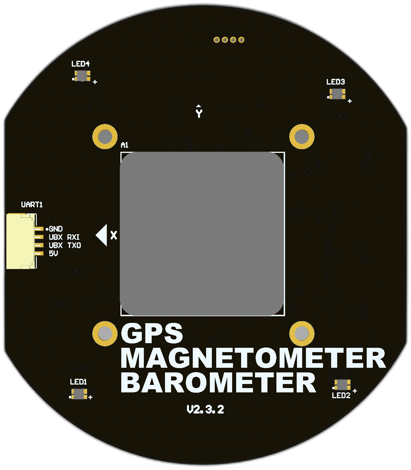 | v0.13.6 (opens new window) (Oct 03, 2024) | v1.6.5 (opens new window) (Dec 19, 2023) | - DroneCAN - Cyphal |
| GNSS v3 (L1/L2 ZED-F9P) 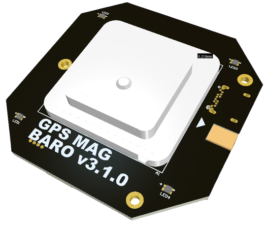 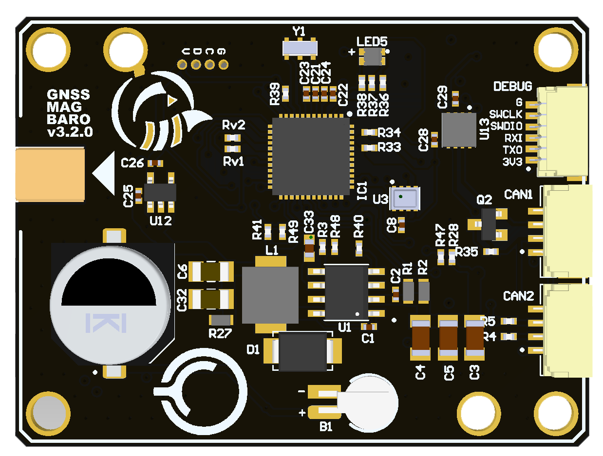 | - | v1.5.4 (opens new window) (Sep 19, 2023) | - DroneCAN - Cyphal |
Mini and Micro 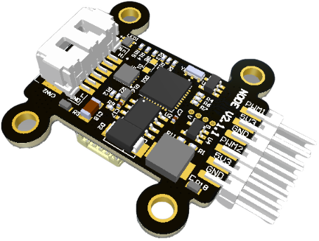 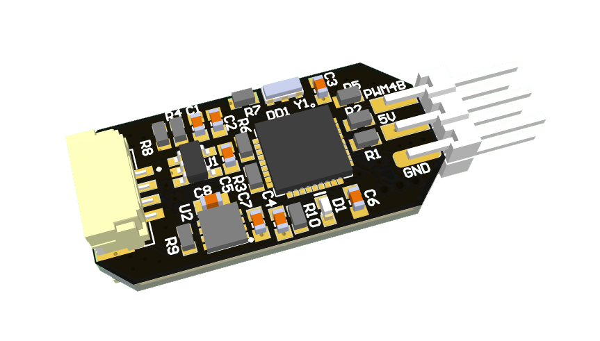 | v0.12.2 (opens new window) (Aug 09, 2023) | v1.5.10 (opens new window) (Nov 17, 2023) | - DroneCAN - Cyphal |
UAV Lights 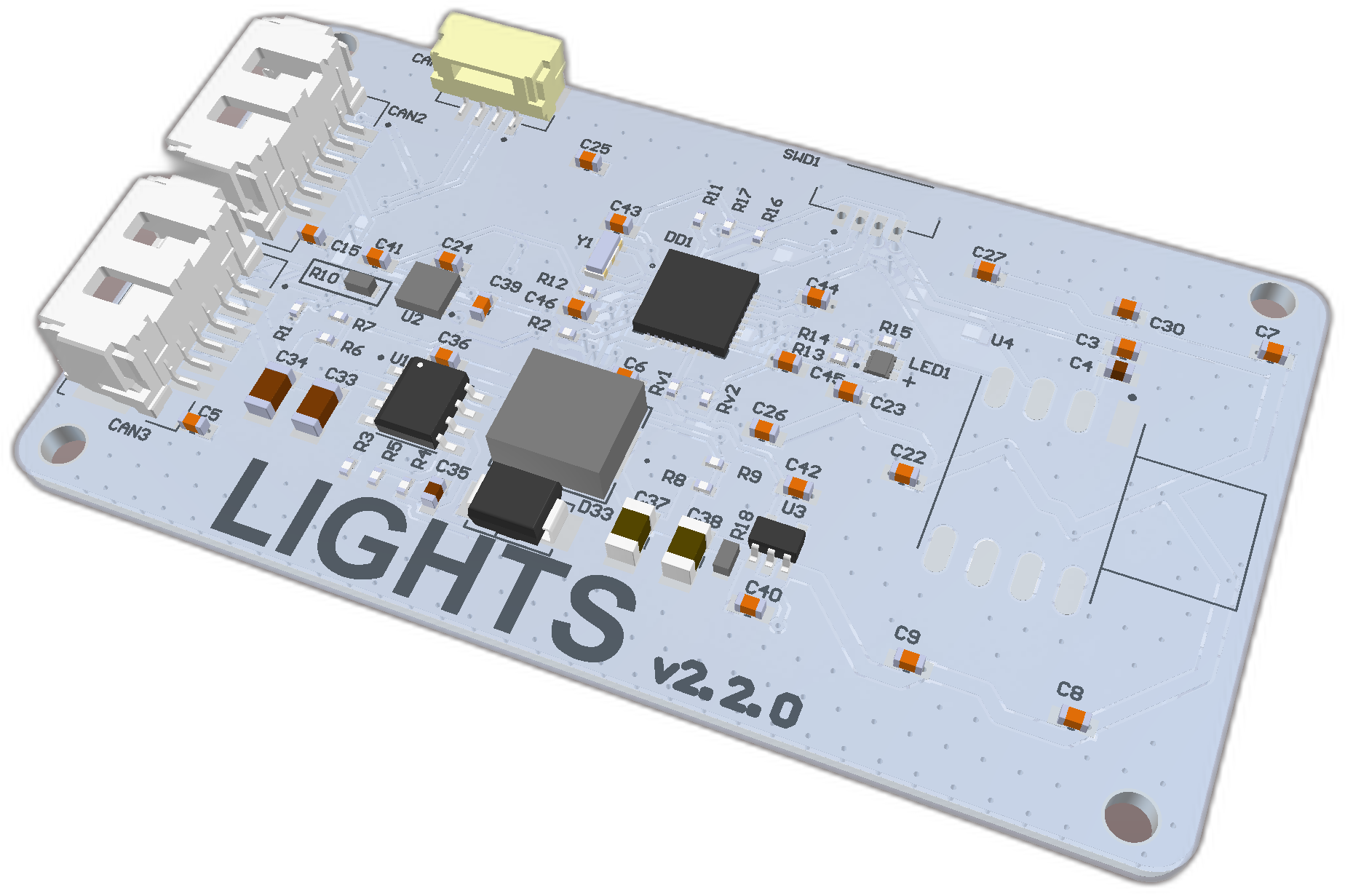 | v0.8.8-stable (opens new window) (Jun 7, 2022) | v0.2.3 (opens new window) (Dec 27, 2023) |
| Device | Cyphal & DroneCAN firmware |
|---|---|
Rangefinder nodes (opens new window) 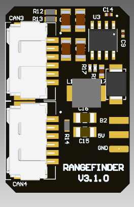 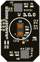 | v1.6.2_a18ac959 (opens new window) (Dec 04, 2023) |
If you want to upload the latest stable firmware or get information about change history, you should check Software Versions page related to the desired board.
# Step 2. Upload firmware
You have a few options here based on what hardware do you have, your OS and preferable software:
| № | Programmer | OS | Software | Tutorial |
|---|---|---|---|---|
| 1 | RL-programmer  | Windows | STM3CubeProgrammer | RL-programmer on Windows with STM3CubeProgrammer |
| 2 | RL-programmer | Ubuntu | st-link | RL-programmer on Linux with stlink |
| 3 | DronecodeProbe 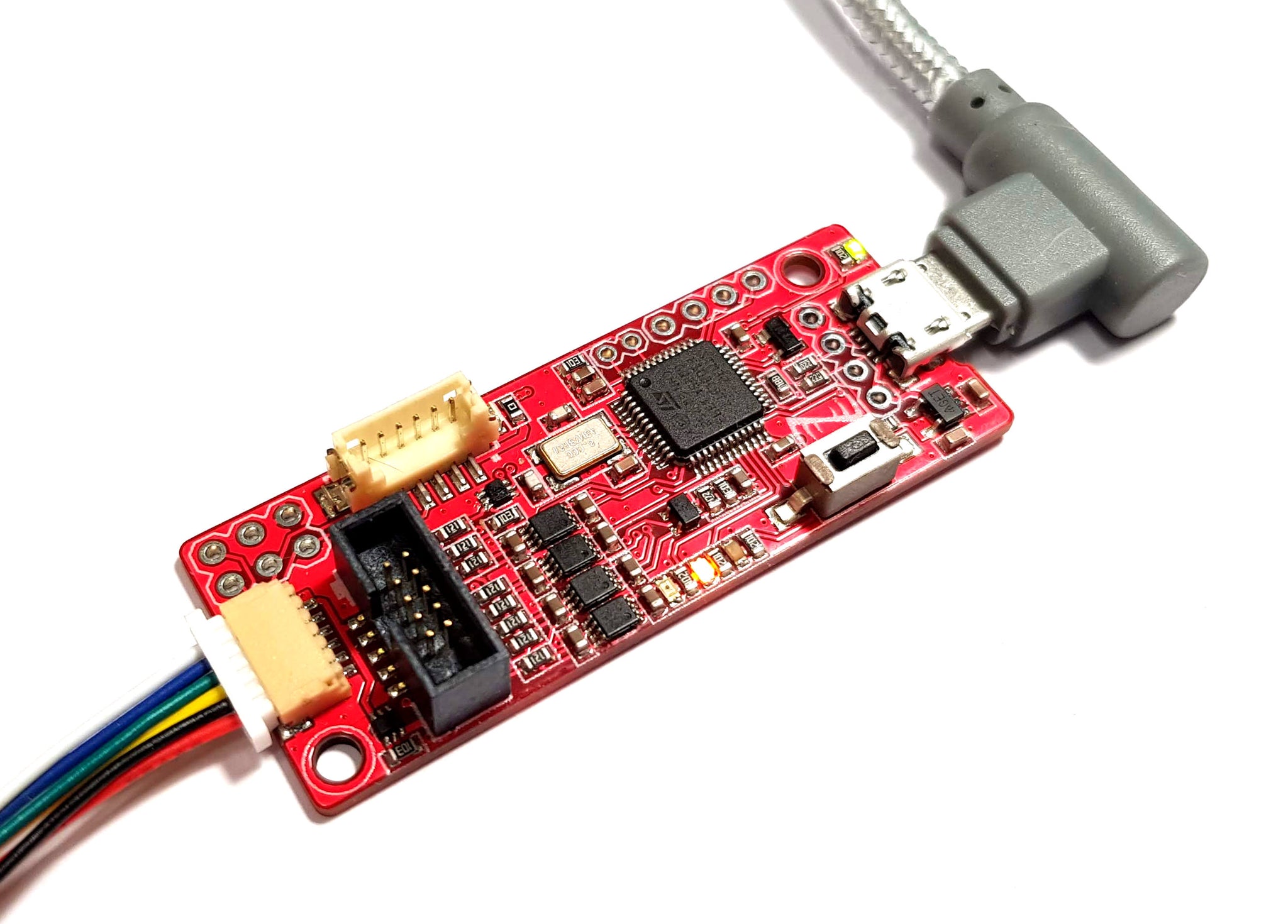 | Ubuntu | Black magic | Dronecode probe on Linux |
| 4 | RL-programmer | Windows | ST-Link utility | RL-programmer on Windows with ST-Link utility |
| 5 | ST-Link | Windows | ST-LINK |