# 4. NODE v3 hardware
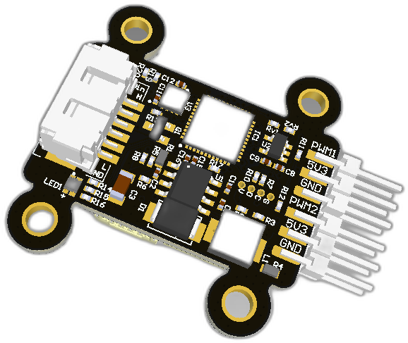
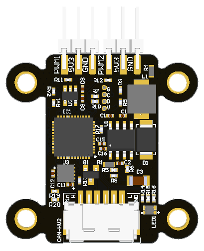
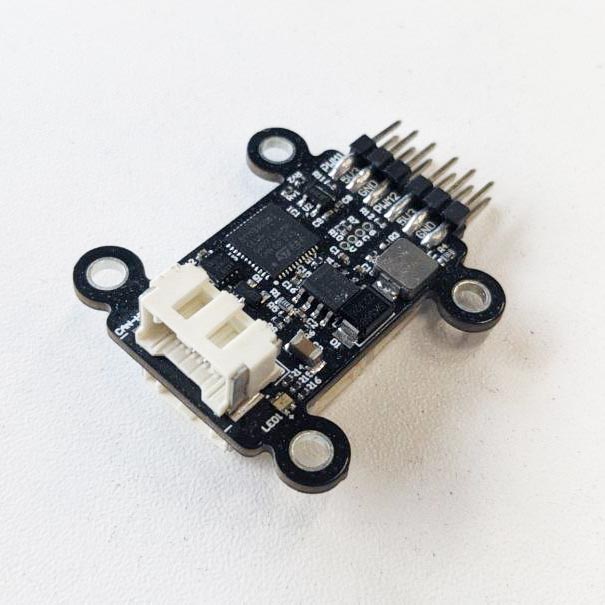
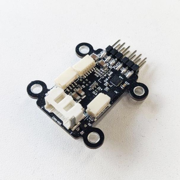
Mini node is the new generation of CAN-PWM converter designed to control up to 4 PWM payloads. Since the node has a built-in DC-DC, a servo can be powered through it. The board also supports receiving feedback from the esc flame over UART or analog signals. The device is also can provide redundancy features for CAN interfaces. And has has MPU-9250 IMU to measure it self accelerations, angular velocity and magnetic field strength. Moreover this device able to commutate terminator resistor to setup bus topology.
 |  |  |
 |  |
# 4.1. Features
- 4 PWM outputs
- 2 ampers thrupass current
- Input voltage sensor
- 5v rail voltage sensor
- standard (SM06B-SRSS-TB(LF)(SN)) debug connector
- up to 2 analog inputs
- CAN connectors: 2 UCANPHY Micro (JST-GH 4), 2 6-pin Molex
- MPU-9250 IMU
- CAN terminator resistors control
- Redundant CAN interface
- built-in DC-DC
- Weight: 6.6 g (with cable 8 g)
- LxWxH: 42.6 x 34.6 x 14.7 mm
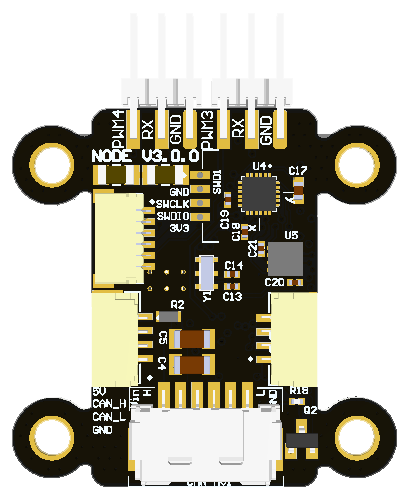
# 4.2. Wire
Connectors
The node has connectors which are described in the table below.
| N | Connector | Description |
|---|---|---|
| 1 | CAN-HV1, CAN-HV2 | Molex-6 connectors |
| 2 | CAN-LV1, CAN-LV2 | JST4 connectors |
| 3 | PWM1, PWM2, PWM3, PWM4 | PWM/GPIO channel, Either 2 UARTs, or 2 ADC or 1 i2C, 5V for servos |
| 4 | SWD1 | Debug connector for SWD |
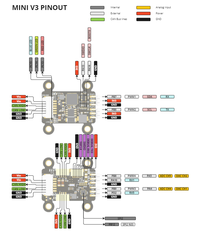
Pin configuration and functions
| Pin N | CAN-HV1 | Pin N | CAN-HV2 | Pin N | CAN-LV1 | Pin N | CAN-LV2 | Pin N | PWM1 | Pin N | PWM2 | Pin N | PWM3 | Pin N | PWM4 | Pin N | SWD1 |
|---|---|---|---|---|---|---|---|---|---|---|---|---|---|---|---|---|---|
| 1 | Vin | 1 | Vin | 1 | 5V | 1 | 5V | 1 | GND | 1 | GND | 1 | GND | 1 | GND | 1 | GND |
| 2 | Vin | 2 | Vin | 2 | CAN2_H | 2 | CAN_H | 2 | 5V | 2 | 5V | 2 | RX5 | 2 | RX | 2 | SWLK |
| 3 | CAN2_H | 3 | CAN_H | 3 | CAN2_L | 3 | CAN_L | 3 | PWM1 | 3 | PWM2 | 3 | PWM3 | 3 | PWM4 | 3 | SWDIO |
| 4 | CAN2_L | 4 | CAN_L | 4 | GND | 4 | GND | 4 | 3.3 | ||||||||
| 5 | GND | 5 | GND | SH1 | GND | SH1 | GND | ||||||||||
| 6 | GND | 6 | GND | SH2 | GND | SH2 | GND | ||||||||||
| P1 | GND | P1 | GND | ||||||||||||||
| P2 | GND | P2 | GND |
Here you can see all connections of MCU.
| MCU PIN | PIN Numer | NET Name | Description |
|---|---|---|---|
| PA7 | 18 | VERSION | |
| PD3 | 41 | TX5 | |
| PA9 | 29 | TX | |
| PA14-BOOT0 | 36 | SWLK | |
| PA13 | 35 | SWDIO | |
| PA12_[PA10] | 34 | STM_USB_DP | |
| PA11_[PA9] | 33 | STM_USB_DM | |
| PF2-NRST | 10 | STM_NRST | |
| PD2 | 40 | RX5 | |
| PA10 | 32 | RX | |
| PA5 | 16 | PWM4 | ADC CH5 |
| PB8 | 47 | PWM4 | |
| PB5 | 44 | PWM3_2 | |
| PB4 | 43 | PWM3_1 | |
| PA4 | 15 | PWM3 | ADC CH4 |
| PB9 | 48 | PWM3 | |
| PB6 | 45 | PWM2 | |
| PB7 | 46 | PWM1 | |
| PC6 | 30 | PC6 | |
| PB15 | 27 | PB15 | CAN2 Terminator |
| PB10 | 22 | PB10 | |
| PB3 | 42 | PB3 | |
| PB2 | 21 | PB2 | |
| PA15 | 37 | PA15 | CAN1 Terminator |
| PA8 | 28 | PA8 | |
| PF1-OSC_OUT | 9 | OSC_OUT | |
| PF0-OSC_IN | 8 | OSC_IN | |
| PB13 | 25 | MPU9250_SCK | MPU9250_SCK |
| PB12 | 24 | MPU9250_CS | MPU9250_CS |
| PB11 | 23 | MOSI/ADC_MID | MPU9250_MOSI |
| PB14 | 26 | MISO/ADC_VC | MPU9250_MISO |
| PC13 | 1 | LED_RED | |
| PC14-OSC32_IN | 2 | LED_GREEN | |
| PC15-OSC32_OUT | 3 | LED_BLUE | |
| PC7 | 31 | INT | |
| PB1 | 20 | FDCAN2_TX | |
| PB0 | 19 | FDCAN2_RX | |
| PD1 | 39 | FDCAN1_TX | |
| PD0 | 38 | FDCAN1_RX | |
| PA2 | 13 | DEBUG_TX | |
| PA3 | 14 | DEBUG_RX | |
| PA0 | 11 | ADC_VIN | |
| PA6 | 17 | ADC_CUR | NC |
| PA1 | 12 | ADC_5V |
# 4.2.3. Specifications
# Mechanical
Scheme is shown on the picture below. CAN model can be provided via email request or issue on github or downloaded on GrabCAD (opens new window).

| Width, mm | Length, mm | Height, mm | |
|---|---|---|---|
| Outline | 27.4 | 42.4 | 14.8 |
| PCB | 22.96 | 34.0 | 2.0 |
Total weight of device less than 50 g.
# Housing
some text about housing
# Absolute Maximum Ratings
| Parameter | MIN | MAX | UNIT |
|---|---|---|---|
| Vin (HV) | 5.5 | 55* | V |
| V (LV) | 4.5 | 5.5 | V |
| I max | 1.0 | A | |
| Operating temperature |
*Noted Voltage should be delivered only with current limitation under 2.5 Amp.
# Recommended operating conditions
| Parameter | Value | UNIT |
|---|---|---|
| Vin (HV) | 30 | V |
| V (LV) | 5 | V |
| I max | A |
# ESD ratings
| Description | Value | UNIT |
|---|---|---|
| Human-body model (HBM) | 2000 | V |
| Charged-device model (CDM) | 500 | V |
# 4.2.4. Integration
Recommended mechanical mounting
Connection example diagram
Both channels are symmetric and should be as follows:
_________
.-----.  |
| I2C |  --- PWM/GPIO
'-----'  --- 5V
         --- GND
.-----.  --- PWM/GPIO
| SWD |  --- UART/ADC
'-----'  --- GND
_________|
# Use case 1. Control and supply 1-2 servos and get feedback from ADC or PWM (input capture)
Mini v2 node                Servo with ADC feedback
_________
.-----.  |                  .------------
| I2C |  --- PWM/GPIO ----- | PWM_IN
'-----'  --- 5V       ----- | 5V
         --- GND      ----- | GND
         --- PWM/GPIO       |
         --- UART/ADC ----- | ADC_OUT
         --- GND            '------------
_________|
# Use case 2. Control and supply 1 servo and get feedback from I2C sensor
Mini v2 node                Servo with ADC feedback
_________
.-----.  |                  .------------
| I2C |  --- PWM/GPIO ----- | PWM_IN
'-----'  --- 5V       ----- | 5V
         --- GND      ----- | GND
         --- PWM/GPIO       '------------
         --- UART/ADC
         --- GND
_________|
# Use case 3. ESC Flame (x2)
Mini v2 node               ESC Flame
_________
.-----.  |
| I2C |  --- PWM/GPIO
'-----'  --- 5V
         --- GND           .------------
         --- PWM/GPIO -----| PWM_IN
         --- UART/ADC -----| UART TX
         --- GND      -----| GND
_________|                 '------------
# Use case 4. ESC Thunder (x2)
Mini v2 node               ESC Thunder
_________
.-----.  |                 .------------
| I2C |  --- PWM/GPIO -----| PWM_IN
'-----'  --- 5V            |
         --- GND      -----| GND
         --- PWM/GPIO -----| 3.3V
         --- UART/ADC -----| UART TX
         --- GND      -----| GND
_________|                 '------------
# Use case 5. Control an actuator (starter, landing station gate, etc) with feedback from a limit switch device (ADC or GPIO input)
Mini v2 node               An actuator
_________
.-----.  |
| I2C |  --- PWM/GPIO
'-----'  --- 5V
         --- GND           .------------
         --- PWM/GPIO -----| GPIO IN
         --- UART/ADC -----| GPIO OUT / ADC
         --- GND      -----| GND
_________|                 '------------
# Use case 6. Control such devices as Starter using GPIO and receiving the feedback from PWM (input capture)
g
# 4.2.5. Power Supply Recommendations
Device is designed to operate from an input voltage supply range between 4.5 V and 5.5 V over CAN2 or CAN3 connector, or 5.5 - 30 V from CAN1. This input supply must be able to withstand the maximum input current and maintain a stable voltage. The resistance of the input supply rail should be low enough that an input current transient does not cause a high enough drop that can cause a false UVLO fault triggering and system reset. The amount of bulk capacitance is not critical, but a 47-μF or 100-μF electrolytic capacitor is a typical choice.
# 4.2.6. Revision history
| View | Version | Description |
|---|---|---|
| v3.0.0 17.05.2024 | Latest version of the board Some other additional info |