# 1. RaccoonLab Mini/Micro nodes
Mini/Micro are general purpose CAN nodes:
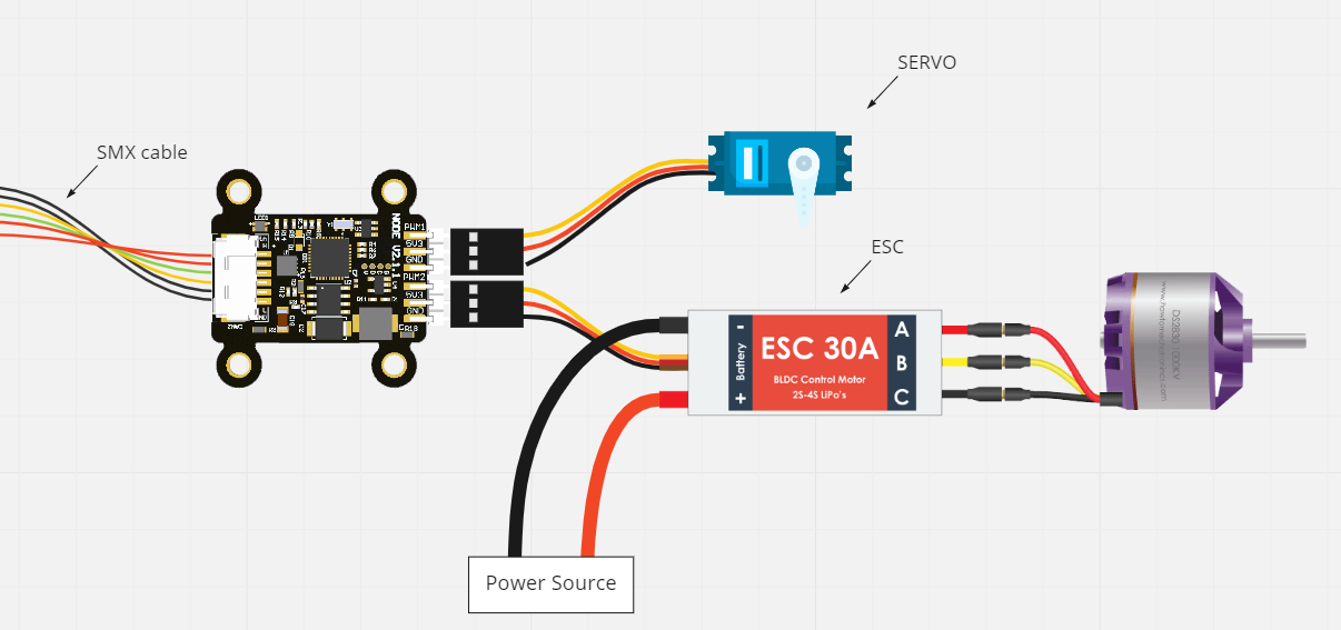
- Micro is the smallest node with 2 groups of pins (PWM/5V/GND) to control 2 servo or ESC.
- Mini v2 has 2 x PWM/5V/GND to control servos or ESCs and 2 x PWM/FB/GND to control and obtain a feedback from ESC via UART.
The devices support different versions of firmware and can be used for different purposes.
Cyphal/DroneCAN CAN-PWM firmwares are default for Mini and Micro nodes. These firmwares convert a typical for PX4/ArduPilot CAN setpoints into PWM to control ESCs or servos. For details, please check the corresponded pages: Cyphal/CAN-PWM, DroneCAN-PWM.
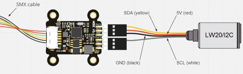
Cyphal&DroneCAN Rangefinder firmware is a single firmware that can work in either Cyphal or DroneCAN mode. It supports LW20/I2C, Garmin Lite v3/I2C and TL-Luna/UART Lidars. For details, please check the Rangefinder page.
DroneCAN fuel tank firmware is based on AS5600 sensor board . For details, please check DroneCAN Fuel Tank.
DroneCAN servo gripper is part of a Mini node template application (opens new window). For details, please check DroneCAN Servo Gripper.
A Custom firmware can be writen by anyone. If you need a custom feature, you can try the Mini node template application (opens new window). You can configure the external pins to work in UART, I2C or ADC mode. From the box, it supports basic Cyphal/DroneCAN features. It has publishers and subscribers as an example.
Which node should I choose?
Briefly, the difference between Mini v2 and Micro can be represented in the table below. Please, check the corresponded pages for more details.
| Mini v2 | Micro | ||
|---|---|---|---|
| Image | 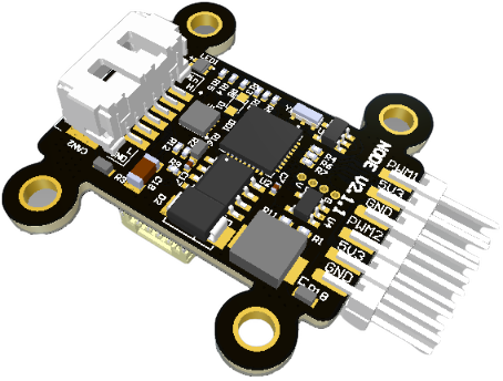 | 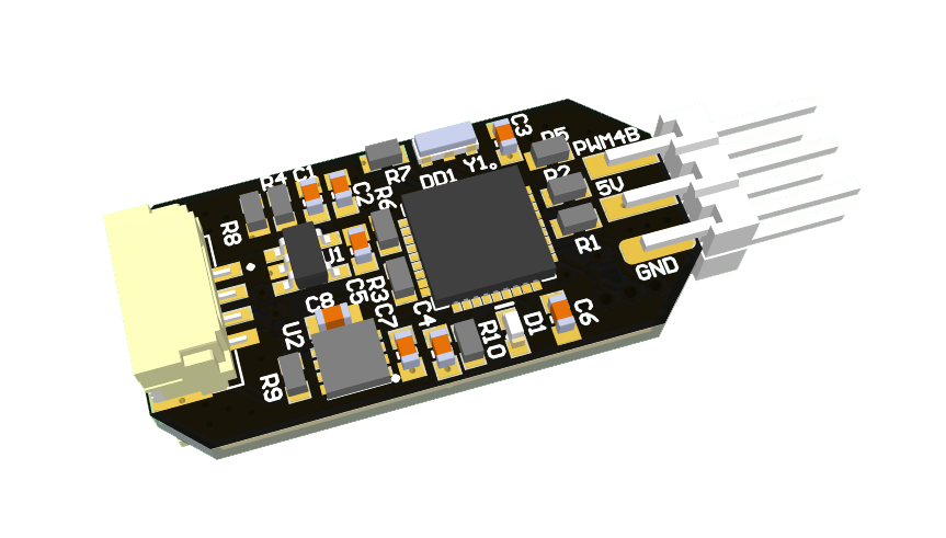 | |
| 1 | Input voltage | 5.5V – 30V | 4.5V – 5.5V |
| 2 | DC-DC | Yes | No |
| 3 | Groups of pins | - PWM+5V+GND x2 - PWM+FB+GND x2 | - PWM+5V+GND x2 |
| 4 | CAN connectors | - UCANPHY Micro x2 - 6-pin Molex x2 | - UCANPHY Micro x2 |
| 5 | SWD interface | + | + |
| 6 | Size, LxWxH, mm | 42x35x12 | 20x10x5 |
| 7 | Mass, g | 5 | 3 |