# 3. Mini v2 node hardware
Mini node is the CAN-PWM converter designed to control 1-4 ESC or servo. Since the node has a built-in DC-DC, a servo can be powered through it. The board also supports receiving feedback from the esc flame.
This page is about hardware specific details. For general information, refer to the 1. General page., for software related details please refer Cyphal interface or DroneCAN interface.
| View | Top view | Bot view |
|---|---|---|
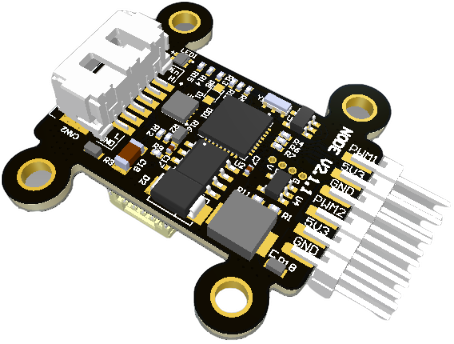 | 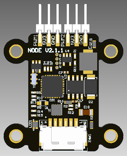 | 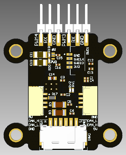 |
# 3.1. Features
- 4 PWM outputs
- 2 ampers thrupass current
- Input voltage sensor
- 5v rail voltage sensor
- CAN connectors: 2 UCANPHY Micro (JST-GH 4) (opens new window), 2 6-pin Molex (opens new window)
- Weight: 6.6 g (with cable 8 g)
- LxWxH: 42x27x12 mm
# 3.2. Wire
Schematic can be provided via e-mail request or issue on github.
Connectors
| № | Connector | Description |
|---|---|---|
| 1 | UCANPHY Micro (JST-GH 4) | Devices that deliver power to the bus are required to provide 4.9–5.5 V on the bus power line, 5.0 V nominal. Devices that are powered from the bus should expect 4.0–5.5 V on the bus power line. The current shall not exceed 1 A per connector. |
| 2 | 6-pin Molex (502585-0670 (opens new window), 502578-0600 (opens new window)) | Contacts support up to 100 V, 2 A per contact. But the board may work only with 2S-6S. |
| 3 | SWD | STM32 firmware updating using programmer-sniffer. |
| 4 | PWM1, PWM2, PWM3, PWM4 | Connectors should be used to deliver signal and power (below 1 amp) to payload such as SERVO or ESC (without power delivery) |
Here (opens new window) you can find manufacturer part number of connectors it self and its mates.
Pin configuration and functions
| Pin | CAN3 | Pin | CAN1, CAN2 | SWD |
|---|---|---|---|---|
| 1 | Vin | 1 | 5V in | GND |
| 2 | Vin | 2 | CAN High | SWCLK |
| 3 | CAN High | 3 | CAN Low | SWDIO |
| 4 | CAN Low | 4 | GND | 3.3V |
| 5 | GND | |||
| 6 | GND |
# 3.3. Specifications
Mechanical
Scheme is shown on the picture below.

| Width, mm | Length, mm | Height, mm | |
|---|---|---|---|
| Outline | 42.4 | 34.6 | 14.3 |
| PCB | 34.0 | 34.6 | 1.6 |
Total weight of device is 6.6 g.
You can download 3D model on GrabCAD (opens new window)
Housing
Information about case presented here.
Absolute Maximum Ratings
| Parameter | MIN | MAX | UNIT |
|---|---|---|---|
| Vin (CAN1) | 5.5 | 55* | V |
| V (CAN2, CAN3) | 4.5 | 5.5 | V |
| I max | A | ||
| Operating temperature |
*Noted Voltage should be delivered only with current limitation under 2.5 Amp.
Recommended operating conditions
| Parameter | Value | UNIT |
|---|---|---|
| Vin (CAN3) | 30 | V |
| V (CAN1, CAN2) | 5 | V |
| I max | A |
ESD ratings
| Description | Value | UNIT |
|---|---|---|
| Human-body model (HBM) | 2000 | V |
| Charged-device model (CDM) | 500 | V |
# 3.4. Description
# Pinout
Here you can see all connections of MCU.

| MCU PIN | Type | Description |
|---|---|---|
| PA0 | INTERNAL ANALOG | Measuring Vin using ADC |
| PA1 | INTERNAL ANALOG | Measuring 5V3 using ADC |
| PB1 | INTERNAL ANALOG | Measuring voltage devider that represents VERSION of hardware using ADC |
| PA11 | INTERNAL DIGITAL | CAN RX |
| PA12 | INTERNAL DIGITAL | CAN TX |
| PA4 | INTERNAL DIGITAL | BLUE LED |
| PA8 | INTERNAL DIGITAL | GREEN LED |
| PA15 | INTERNAL DIGITAL | RED LED |
| PA13 | EXTERNAL DEBUG | SWDIO |
| PA14 | EXTERNAL DEBUG | SWCLK |
| PB7 | EXTERNAL DIGITAL | PWM1 / SDA / RX1 |
| PB6 | EXTERNAL DIGITAL | PWM2 / SCL / TX1 |
| PB4 | EXTERNAL DIGITAL | PWM3 |
| PA2 | EXTERNAL DIGITAL/ANALOG | TX2 (RX2 in one wire mode) / ADC CH2 |
| PB5 | EXTERNAL DIGITAL | PWM4 |
| PA10 | EXTERNAL DIGITAL | RX1 |
# Functional Block Diagram

# Connection example diagram

# 3.5. Power Supply Recommendations
Device is designed to operate from an input voltage supply range between 4.5 V and 5.5 V over CAN-LV connector, or 5.5 - 30 V from CAN-HV. This input supply must be able to withstand the maximum input current and maintain a stable voltage. The resistance of the input supply rail should be low enough that an input current transient does not cause a high enough drop that can cause a false UVLO fault triggering and system reset. The amount of bulk capacitance is not critical, but a 47-μF or 100-μF electrolytic capacitor is a typical choice.
# 3.6. Revision history
| View | Version | Date | Description |
|---|---|---|---|
| v2.1.1 | Oct 9, 2022 | Add back diode to 5v LDO |
| v2.0 | Jun 12, 2022 | Add RGB LED, make smaller topology of PCB. Note: can't be powered from CAN jst-4 pins connector |
 | v1.0 | 2021 | First version |