# Wires
Its used Silicone Rubber Cable UL3239 (opens new window) standard wires for wire assemblies. Initial standard is presented on ul.com (opens new window) web site. Its highly recomended to use Q/IRMV2-2008, UL758 (opens new window) (or UL758-2000REV (opens new window)) for wires in future.
Cable characteristics:
- Type: two twisted pairs, or one twisted pair plus one straight pair
- Twisting pitch: 0.3–1 twists per centimeter
- Wire gauge: #28 AWG
- Wire strands: 7/0.12TS or 16/0.08TS
- Wire Insulation thickness: 0.42 to 1 mm
- Conductor material: copper
The following table provides an overview of the currently used connector types.
| Connector name | Base connector type | Bus power | compatible standards |
|---|---|---|---|
| JST 4-pins cable (SJT170R) | JST GH 4-circuit | 5 V, 1 A | Dronecode Autopilot Connector Standard (opens new window) |
| JST 4-pins cable (SJT250R) | JST GH 4-circuit | 5 V, 1 A | |
| JST 4-pins cable (SJT500R) | JST GH 4-circuit | 5 V, 1 A | |
| Molex 6-pins Cable (SMX150R) | Molex 6-pin | 30 V, 2 A | This standard |
| Molex 6-pins Cable (SMX250R) | Molex 6-pin | 30 V, 2 A | This standard |
| Molex 6-pins Cable (SMX500R) | Molex 6-pin | 30 V, 2 A | This standard |
| Molex 6-pins Cable (SMX100R) | Molex 6-pin | 30 V, 2 A | This standard |
| SJT170DB | JST GHR-04V-S to SHR-06V-S | Zubax probe (opens new window) |
# Molex 6-pins Cable (SMX R)
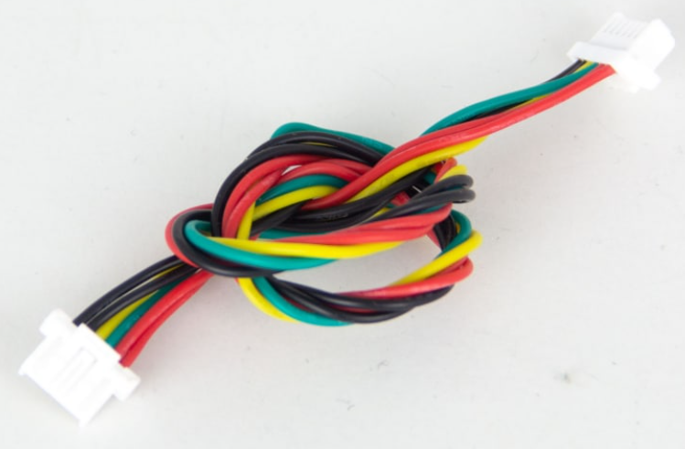
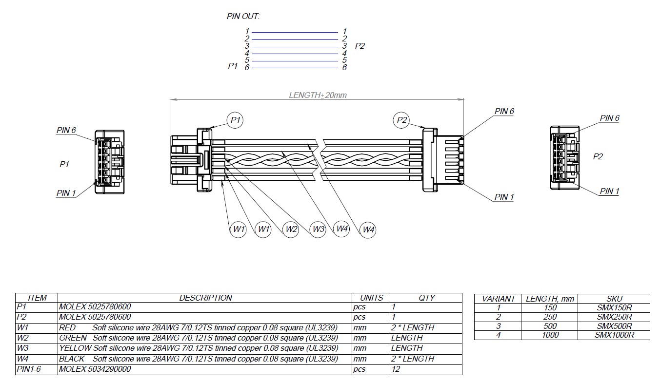
This pinout should be used for any CAN ports. In case of developing vehicle thet outline dimensions grater than 0.5 m its recomended to use self sufficient devices with voltage regulator on board. In this case port should be able to transfer needed power. Recommended connector is MOLEX 502585-0670 (opens new window) and it mates with MOLEX 6-pins cable (opens new window), and it can be assembled by you self using MOLEX housing 5025780600 (opens new window) and 6 pins 5025790000 (opens new window).
| Pin | Signal | Max voltage |
|---|---|---|
| 1 | Vin | 60 |
| 2 | Vin | 60 |
| 3 | CAN High | 60 |
| 4 | CAN Low | 60 |
| 5 | GND | GND |
| 6 | GND | GND |


# JST 4-pins cable (SJT R)
The Micro connector is intended for weight- and space-sensitive applications. It is a board-level connector, meaning that it can be installed on the PCB rather than on the panel.
The Micro connector is compatible with the Dronecode Autopilot Connector Standard. This connector type is recommended for small UAV and nanosatellites. It is also the recommended connector for attaching external panel-mounted connectors (such as the M8 or D-Sub types) to the PCB inside the enclosure.
In case of using low power devices and small vehicle. And in the way of compatibility with PX4 standards its recommended to use 4 pin JST SM04B-GHS-TB(LF)(SN) connector that suits with JST 4-pins cable (opens new window). And can be assembled using next PN: JST GHR-04V-S (opens new window) and pin SSHL-002T-P0.2 (opens new window).
| Pin | Signal | Max. voltage |
|---|---|---|
| 1 | Vcc | 5.5V |
| 2 | CAN High | 3.3V |
| 3 | CAN Low | 3.3V |
| 4 | GND | GND |
| Pin | Signal | Max. voltage |
|---|---|---|
| 1 | Vcc | 5.5V |
| 2 | SBUS | 3.3V |
| 3 | RSSI | 3.3V |
| 4 | GND | GND |
| Pin | Signal | Max. voltage |
|---|---|---|
| 1 | Vcc | 5.5V |
| 2 | SCL | 3.3V |
| 3 | SDA | 3.3V |
| 4 | GND | GND |
| Pin | Signal | Max. voltage |
|---|---|---|
| 1 | 3.3V | 3.3V |
| 2 | SWDIO | 3.3V |
| 3 | SWCLK | 3.3V |
| 4 | GND | GND |
Devices that deliver power to the bus are required to provide 5.0—5.5 V on the bus power line. The anticipated current draw is up to 1 A per connector.
Devices that are powered from the bus should expect 4.0—5.5 V on the bus power line. The maximum recommended current draw from the bus is 500 mA per device.
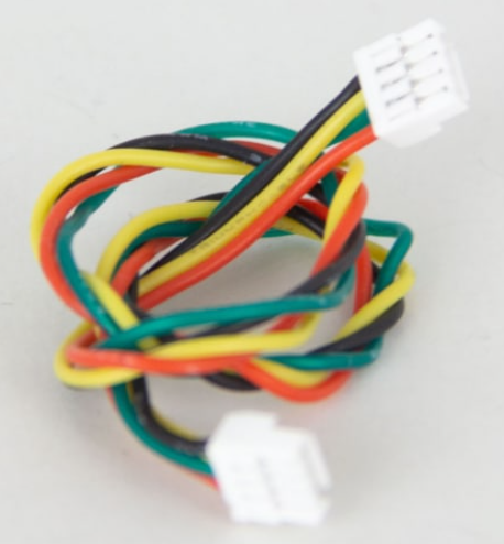
Photo of this type of wire presented below.

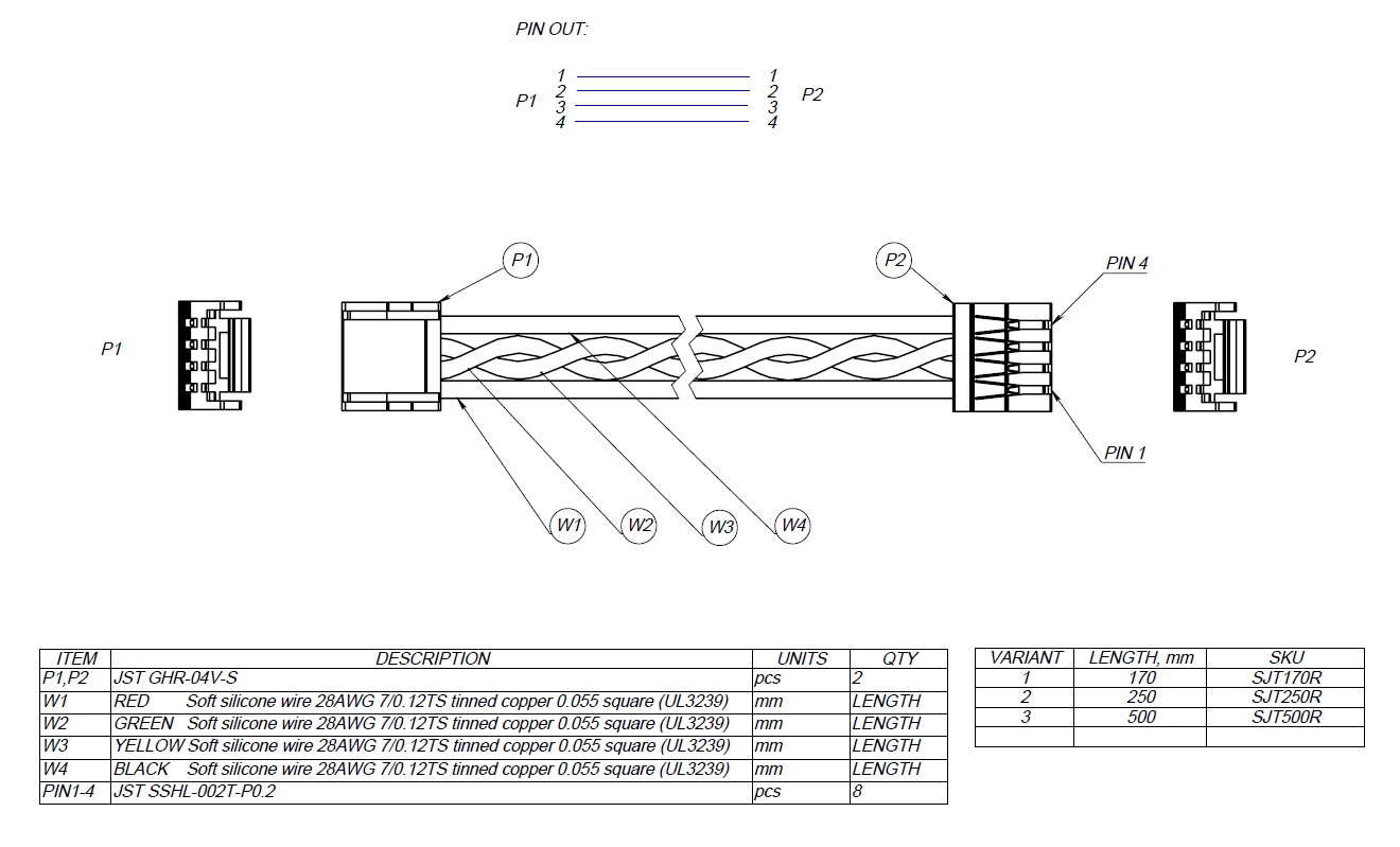
Mechanical drawing is presented here.

# JST 6-pins cable (SJT R)
| Pin | Signal | Max. voltage |
|---|---|---|
| 1 | Vcc | 5.5V |
| 2 | RXI | 3.3V |
| 3 | TXO | 3.3V |
| 4 | RTS | 3.3V |
| 5 | CTS | 3.3V |
| 6 | GND | GND |
| Pin | Signal | Max. voltage |
|---|---|---|
| 1 | Vcc | 5.5V |
| 2 | CLK | 3.3V |
| 3 | MISO | 3.3V |
| 4 | MOSI | 3.3V |
| 5 | SS1 | 3.3V |
| 6 | GND | GND |