# RFD900 Holder
| View | Top | Bottom |
|---|---|---|
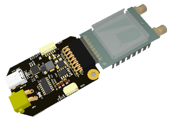 | 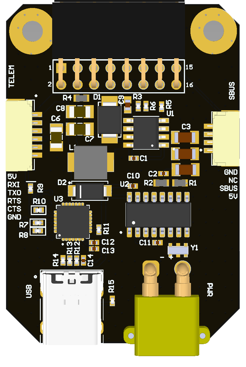 | 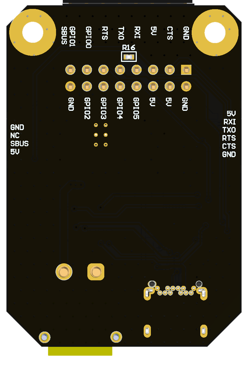 |
 |  |
# TODO
ADD INFORMATION ABOUT
- ONBOARD VERSION
- SETUP
# Features
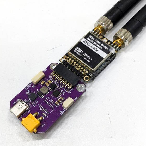
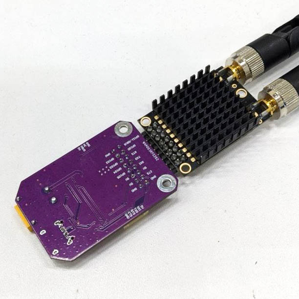
This board is developed to directly connect RFD900 (opens new window) radio module to PC ovar USB-UART converter.
# Wiring
Schematic can be found in this (opens new window) repo on GitHub.
Connectors
The node has connectors which are described in the table below.
| N | Connector | Description |
|---|---|---|
| 1 | SBUS | Used to connect RC control |
| 2 | TELEM | Used to get telemetry on ttl level |
| 3 | PWR | Used to externaly power up modem from 2-6S battery |
| 4 | USB | Used to get telemetry via VCP on PC |
Here (opens new window) you can find manufacturer part number of connectors it self and its mates.
# Pin configuration and functions
| Pin N | SBUS | Pin N | TELEM |
|---|---|---|---|
| 1 | 5V | 1 | 5V |
| 2 | GPIO1/SBUS | 2 | RXI_RFD |
| 3 | NC | 3 | TXO_RFD |
| 4 | GND | 4 | RTS |
| 5 | CTS | ||
| 6 | GND |
# Specifications
Mechanical
Scheme is shown on the picture below. Model can be downloaded here (opens new window) repo on GitHub.
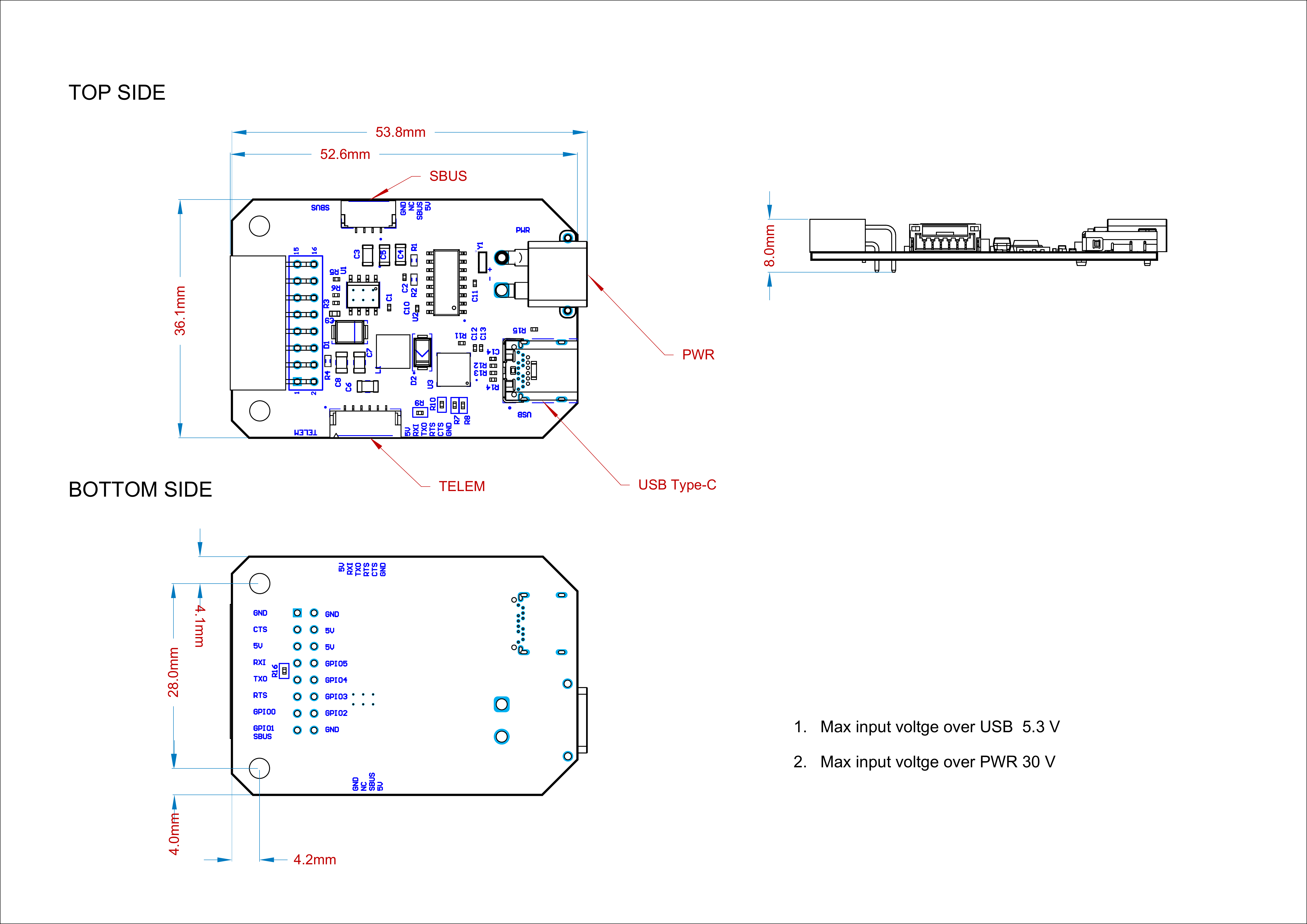
| Width, mm | Length, mm | Height, mm | |
|---|---|---|---|
| Outline | 36.1 | 106.6 | 13.7 |
| PCB | 36.1 | 52.35 | 1.2 |
Total weight of device less than 50 g.
# Housing
Information about case presented here.
# Absolute Maximum Ratings
| Parameter | MIN | MAX | UNIT |
|---|---|---|---|
| Vin (PWR) | 5.5 | 55* | V |
| Vusb | 4.5 | 5.5 | V |
| I max @ 5V | 0.1 | 0.6 | A |
| Operating temperature | -40 | +60 | C |
*Noted Voltage should be delivered only with current limitation under 2.5 Amp.
# Recommended operating conditions
| Parameter | Value | UNIT |
|---|---|---|
| Vin (PWR) | 30 | V |
| Vusb | 5 | V |
# ESD ratings
| Description | Value | UNIT |
|---|---|---|
| Human-body model (HBM) | 2000 | V |
| Charged-device model (CDM) | 500 | V |
# MTFF
# Integration
Recommended mechanical mounting
Connection example diagram
# Power Supply Recommendations
Device is designed to operate from an input voltage supply range between 4.5 V and 5.5 V over USB connector, or 5.5 - 30 V from PWR. This input supply must be able to withstand the maximum input current and maintain a stable voltage. The resistance of the input supply rail should be low enough that an input current transient does not cause a high enough drop that can cause a false UVLO fault triggering and system reset. The amount of bulk capacitance is not critical, but a 47-uF or 100-uF electrolytic capacitor is a typical choice.
# Revision history
| View | Version | Date | Description |
|---|---|---|---|
| master (opens new window) | June 26, 2023 | Variant for onboard usage | |
| USB-UART (opens new window) | Sep 6, 2023 | Variant for Ground station use |
← picoNODE