# Jetson Xavier NX HAT
The board is designed for connecting CAN bus to Jetson Xavier NX (opens new window). It gives access to Cyphal (opens new window)/DroneCAN (opens new window) (old name UAVCAN)
| View | Top | Bottom |
|---|---|---|
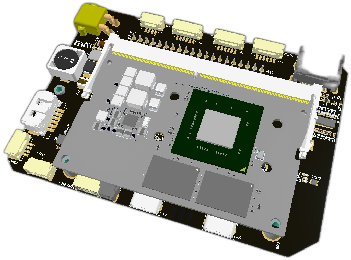 | 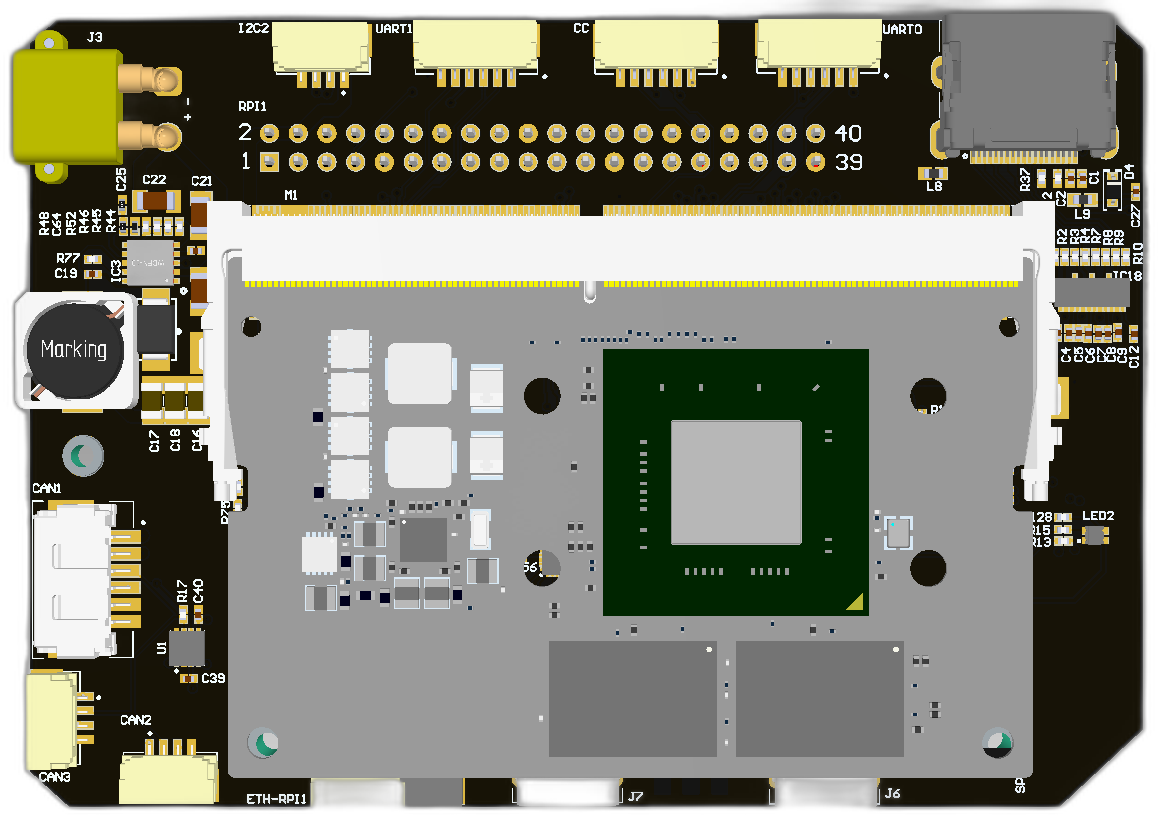 | 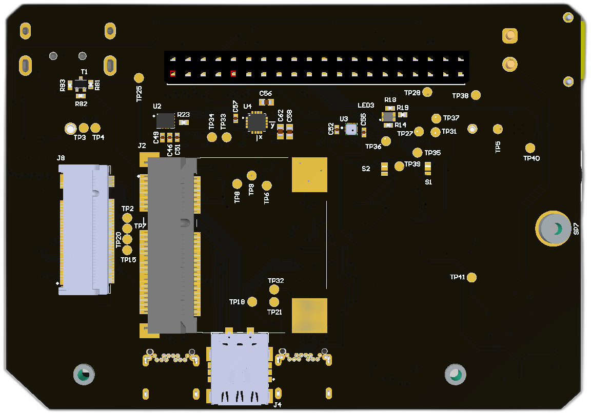 |
 | 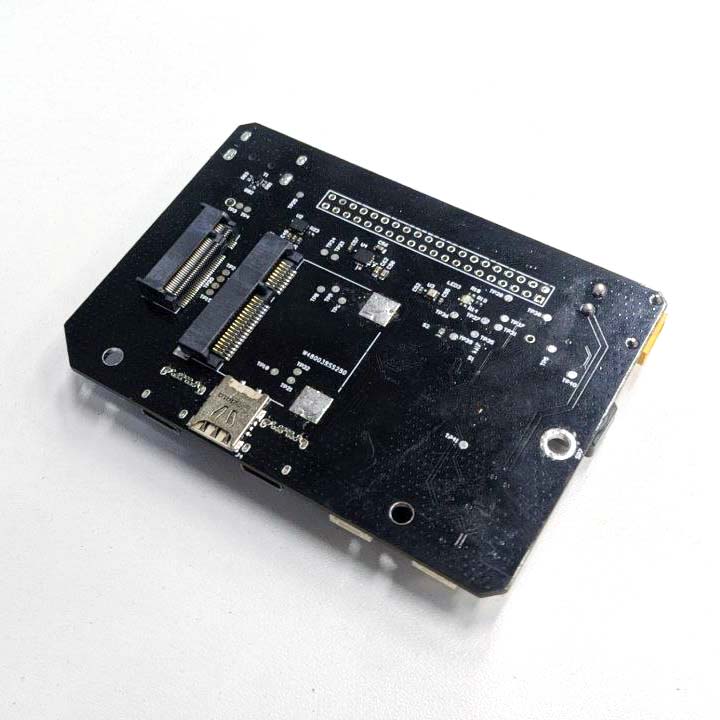 |
# Features
- Jetson NX
# Wiring
Schematic features. Schematic can be provided via issue.
Connectors
The node has connectors which are described in the table below.
| N | Connector | Description |
|---|---|---|
| 1 | CAN1 | |
| 2 | CAN2, CAN3, ETH-RPI1, I2C2 | |
| 3 | CC, UART0, UART1 | |
| 4 | ETH-RPI? | |
| 5 | J1 | |
| 6 | J2 | |
| 7 | J3 | |
| 8 | J4 | |
| 9 | J6, J7 | |
| 10 | J8 | |
| 11 | RPI1 |
Here (opens new window) you can find manufacturer part number of connectors it self and its mates.
Pin configuration and functions
Pin configuration for NX
| GPIO | Defedition |
|---|
Jetson NX pinmap (opens new window)
# Specifications
Mechanical
Scheme is shown on the picture below. CAN model can be provided via email request or issue on github or downloaded on GrabCAD (opens new window).
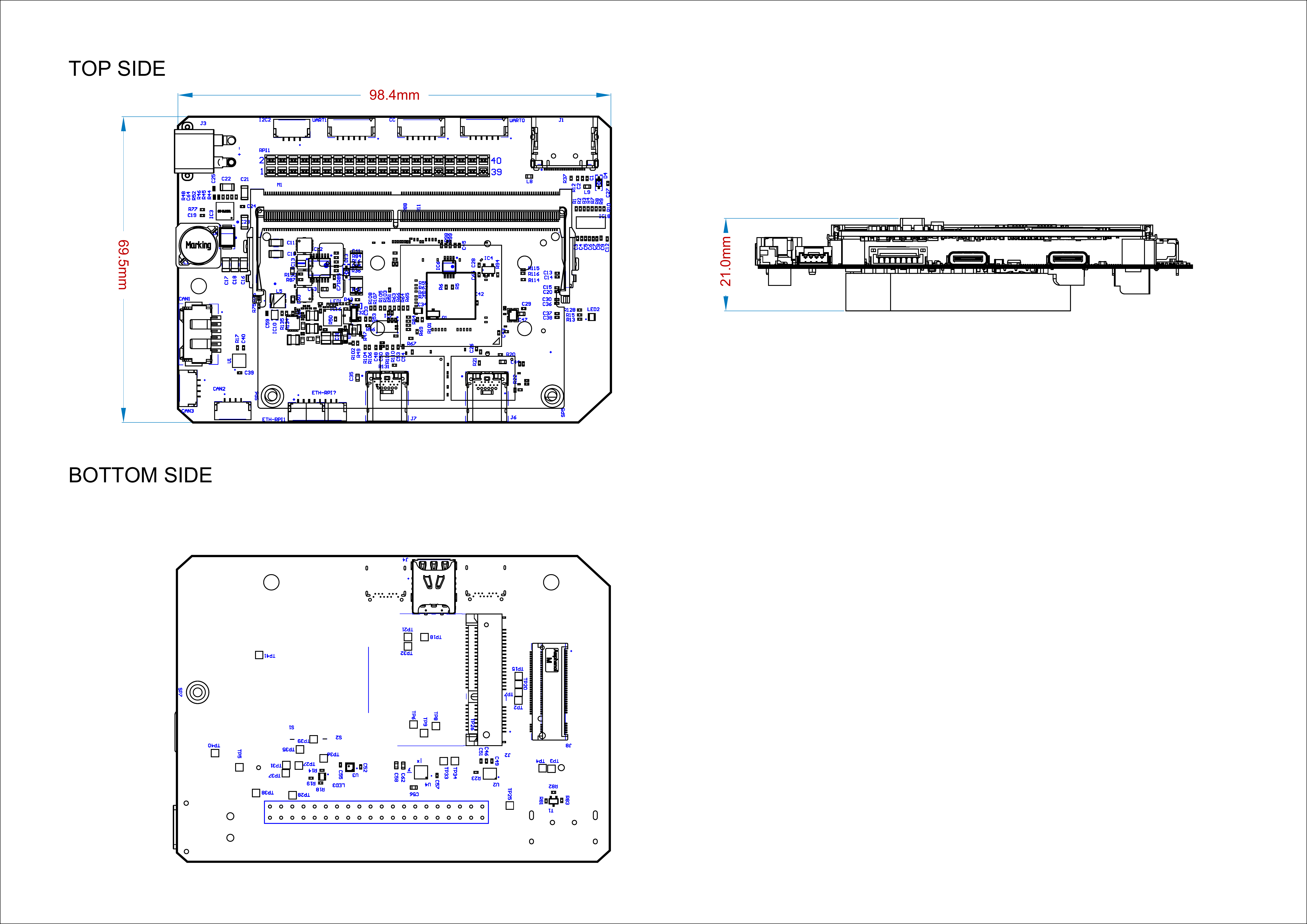
| Width, mm | Length, mm | Height, mm | |
|---|---|---|---|
| Outline | 99.2 | 69.5 | 19.7 |
| PCB | 98.38 | 69.49 | 0.4 |
Total weight of device less than 50 g.
Housing
Information about case presented here.
Absolute Maximum Ratings
| Parameter | MIN | MAX | UNIT |
|---|---|---|---|
| Vin (CAN1) | 5.5 | 55* | V |
| V (CAN2, CAN3) | 4.5 | 5.5 | V |
| I max | A | ||
| Operating temperature |
*Noted Voltage should be delivered only with current limitation under 2.5 Amp.
Recommended operating conditions
| Parameter | Value | UNIT |
|---|---|---|
| Vin (CAN3) | 30 | V |
| V (CAN1, CAN2) | 5 | V |
| I max | A |
ESD ratings
| Description | Value | UNIT |
|---|---|---|
| Human-body model (HBM) | 2000 | V |
| Charged-device model (CDM) | 500 | V |
# MTFF
# Integration
Recommended mechanical mounting
Connection example diagram
# Power Supply Recommendations
Device is designed to operate from an input voltage supply range between 4.5 V and 5.5 V over CAN2 or CAN3 connector, or 5.5 - 30 V from CAN1. This input supply must be able to withstand the maximum input current and maintain a stable voltage. The resistance of the input supply rail should be low enough that an input current transient does not cause a high enough drop that can cause a false UVLO fault triggering and system reset. The amount of bulk capacitance is not critical, but a 47-uF or 100-uF electrolytic capacitor is a typical choice.
# 2. Led indication
# LTE Modem connection setup
Instruction based of this (opens new window) instruction.
- Install LTE modem like this (opens new window) in to the board
- Check that device is powered and visible by system
$ lsusb
In case of Quectel EC25-E 3G/4G modem you should see something like this:
Bus 002 Device 001: ID 1d6b:0003 Linux Foundation 3.0 root hub
Bus 001 Device 002: ID 2c7c:0125
Bus 001 Device 001: ID 1d6b:0002 Linux Foundation 2.0 root hub
- Check where LTE modem is mapped
dmesg | grep ttyUSB
[   10.091065] usb 1-3: GSM modem (1-port) converter now attached to ttyUSB0
[   10.091490] usb 1-3: GSM modem (1-port) converter now attached to ttyUSB1
[   10.112659] usb 1-3: GSM modem (1-port) converter now attached to ttyUSB2
[   10.114288] usb 1-3: GSM modem (1-port) converter now attached to ttyUSB3
Commonly ttyUSB1 is GNSS and ttyUSB2 is for LTE.
- Check that device is accesble from minicom like in this (opens new window) instruction:
sudo minicom -D /dev/ttyUSB2
After you type AT you should see next reply (AT+CPIN? is to check SIM card is ready):
AT
OK
AT+CPIN?
+CPIN: READY
- Install
wvdialpacage:sudo apt-get install wvdial - Edit config
sudo pico /etc/wvdial.conf:
[Dialer Defaults]
Init1 = ATZ
Init2 = ATQ0 V1 E1 S0=0
Modem Type = Analog Modem
Baud = 9600
New PPPD = yes
Modem = /dev/ttyUSB2
ISDN = 0
Phone = *99#
Password = internet
Username = internet
Stupid Mode = on
- Testing the dial up by run
sudo wvdial. Success dial up screen-print:
--> WvDial: Internet dialer version 1.61
--> Initializing modem.
--> Sending: ATZ
--> Sending: ATQ0
--> Re-Sending: ATZ
OK
--> Sending: ATQ0 V1 E1 S0=0 &C1 &D2 +FCLASS=0
ATQ0 V1 E1 S0=0 &C1 &D2 +FCLASS=0
OK
--> Modem initialized.
--> Sending: ATDT*99#
--> Waiting for carrier.
ATDT*99#
CONNECT 150000000
--> Carrier detected.  Starting PPP immediately.
--> Starting pppd at Mon Oct  9 17:35:48 2023
--> Pid of pppd: 8702
--> Using interface ppp0
--> local  IP address xxx.xxx.xxx.xxx
--> remote IP address xxx.xxx.xxx.xxx
--> primary   DNS address xxx.xxx.xxx.xxx
--> secondary DNS address xxx.xxx.xxx.xxx
Ping on other console window:
ping -I ppp0 google.comFor auto connect make the service
sudo pico /etc/systemd/system/wvdial.service
[Unit]
Description=wvdial

[Service]
ExecStart=/usr/bin/wvdial
Restart=on-failure
RestartSec=5
Add the code to the 99-com.rules file. It will call the wvdial.service when the USB modem loaded.
sudo pico /etc/udev/rules.d/99-com.rules
SUBSYSTEM=="tty", KERNEL=="ttyUSB2", TAG+="systemd", ENV{SYSTEMD_WANTS}+="wvdial.service"
- To test the service type
ifconfigand you will see line like:
ppp0: flags=4305<UP,POINTOPOINT,RUNNING,NOARP,MULTICAST> mtu 1500
# Useful links:
# Inspired by
# Revision history
| View | Version | Date | Description |
|---|