# AS5600 sensor board
Board designed to connect to THIS (opens new window) board as beedback sensor for any servo motor driven mechanism, for example plane elerone or rudder.
You can find Specs of the chip in datasheet (opens new window) for sensor.
# Features
The AS5600 is ideally suited for contactless potentiometers, contactless knobs, pedals, RC servos and other angular position measurement solutions.
- 12 bit resolution
- Dimensions: 17.2 x 18 x 5.3 mm
| View | Top view | Bot view |
|---|---|---|
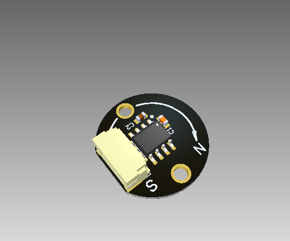 | 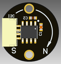 | 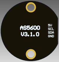 |
# Wire
Schematic is presented here.
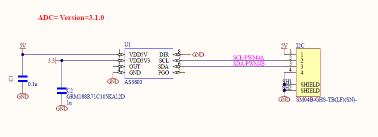
Connectors
The node has 3 connectors which are described in the table below.
| № | Connector | Description |
|---|---|---|
| 1 | I2C | Main I2C and power port |
In paragraph Wire mating (opens new window) you can find manufacturer part number of connectors it self and its mates.
| Type | MP | Suitable Wire Type | MP |
|---|---|---|---|
| I2C | JST SM04B-GHS-TB(LF)(SN) | JST 4-pins cable (opens new window) | JST GHR-04V-S (opens new window) and pin SSHL-002T-P0.2 (opens new window) |
Pin configuration and functions
| Pin N | I2C |
|---|---|
| 1 | 5V in |
| 2 | SCL |
| 3 | SDA |
| 4 | GND |
# Specifications
Mechanical
Scheme is shown on the picture below.
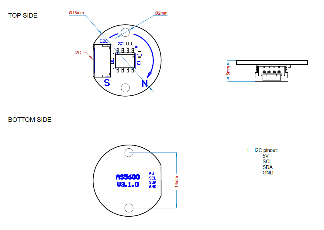
| Width, mm | Length, mm | Height, mm | |
|---|---|---|---|
| Outline | 17.2 | 18 | 5.3 |
| PCB | 17.2 | 18 | 1.6 |
Total weight of device less than X g.
You can download 3D model on GrabCAD (opens new window)
Absolute Maximum Ratings
| Parameter | MIN | MAX | UNIT |
|---|---|---|---|
| Vin | -0.3 | 6.1 | V |
| I max | -100 | 100 | mA |
| Wide temperature range | -40 | 125 | °C |
Recomended operating conditions
| Parameter | VALUE | UNIT |
|---|---|---|
| Vin | 5 | V |
| I max | -100 | 100 |
| Wide temperature range | -40 | 125 |
ESD ratings
| Description | Value | UNIT |
|---|---|---|
| Human-body model (HBM) * | 1000 | V |
| Charged-device model (CDM) * | 1000 | V |
*MIL 883 E method 3015.7 (opens new window)
# Description
Connection example diagram
# Power Supply Recommendations
The uNODE is designed to operate from an input voltage supply range between 4.5 V and 5.5 V. This input supply must be able to withstand the maximum input current and maintain a stable voltage. The resistance of the input supply rail should be low enough that an input current transient does not cause a high enough drop that can cause a false UVLO fault triggering and system reset. The amount of bulk capacitance is not critical, but a 47-μF or 100-μF electrolytic capacitor is a typical choice.
# Revision history
| version | Description |
|---|---|
| v3.1.0 | First produced board |