# 4. Cyphal PWM node
This page is about Cyphal related details such as interface, supported features, registers, configuration and usage examples and software versions. For general information please refer to the 1. General page, for hardware related details including wiring examples please refer to the uNode or Mini v2 pages.
# 4.1. Cyphal interface
This node interacts with the following data types:
Common for any node
| № | Type | Message |
|---|---|---|
| 1 | publisher | uavcan.node.Heartbeat (opens new window) |
| 2 | RPC-service | uavcan.node.GetInfo.Response (opens new window) |
| 3 | RPC-service | uavcan.node.ExecuteCommand (opens new window) |
| 4 | RPC-service | uavcan.register.List (opens new window) |
| 5 | RPC-service | uavcan.register.Access (opens new window) |
| 6 | publisher | uavcan.node.port.List (opens new window) |
Here ExecuteCommand supports COMMAND_RESTART=65535, COMMAND_FACTORY_RESET=65532 and COMMAND_STORE_PERSISTENT_STATES=65530.
Actuator (Esc/Servo) service
This node supports the UDRAL Actuator (ESC/Servo) service (opens new window). It uses the following subjects:
| № | Type | Message | Topic name |
|---|---|---|---|
| 1 | subscriber | reg.udral.service.actuator.common.sp/* (opens new window) | setpoint |
| 2 | subscriber | reg.udral.service.common.Readiness.0.1 (opens new window) | readiness |
| 3 | publisher | reg.udral.service.actuator.common.Feedback.0.1 (opens new window) | feedback |
Circuit status service
Like any other RaccoonLab node, this node also supports the Circuit status service. It uses the following subjects:
| № | Type | Message | Topic name |
|---|---|---|---|
| 1 | pub | uavcan.si.sample.voltage.Scalar.1.0 | crct.5v |
| 2 | pub | uavcan.si.sample.voltage.Scalar.1.0 | crct.vin |
| 3 | pub | uavcan.si.sample.temperature.Scalar.1.0 | crct.temp |
TIP
Since uNode doesn't have an internal DC-DC, it doesn't provide Vin voltage.
# 4.2. Cyphal Registers
The node with the latest v1.5.10 software has the following non port related registers:
| № | Register name | Description |
|---|---|---|
| 1 | uavcan.node.id | Defines a node-ID. Allowed values [0,127]. |
| 2 | system.name | Defines custom node name. If empty, the node will use the default name. |
| 3 | uavcan.node.description | User/integrator-defined, human-readable description of this specific node. |
| 4 | pwm.ttl_ms | Time to live (read about CONTROL_TIMEOUT here (opens new window)) |
| 5 | pwm.control_mode | Control mode (opens new window): 0 - ratiometric [0; 1.0] 1 - PX4 DroneCAN legacy [0; 8192] |
| 6 | pwm*.ch | Index of Vector31 setpoint: 0-30 - enabled 255 - disabled |
| 7 | pwm*.min | PWM duration when setpoint is min |
| 8 | pwm*.max | PWM duration when setpoint is max |
| 9 | pwm*.def | PWM duration when setpoint is not present or device is not engaged |
Click here to show the full registers list of mini v2 node with cyphal v1.5.10 software.
The registers and their values below were received by executing the commands:
y cmd 50 65532
y cmd 50 65535
y rl 50 | y rb 50 | jq > registers.json
{
  "pwm.control_mode": 0,
  "pwm.ttl_ms": 500,
  "pwm1.ch": 255,
  "pwm1.def": 1000,
  "pwm1.max": 2000,
  "pwm1.min": 1000,
  "pwm2.ch": 255,
  "pwm2.def": 1000,
  "pwm2.max": 2000,
  "pwm2.min": 1000,
  "pwm3.ch": 255,
  "pwm3.def": 1000,
  "pwm3.max": 2000,
  "pwm3.min": 1000,
  "pwm4.ch": 255,
  "pwm4.def": 1000,
  "pwm4.max": 2000,
  "pwm4.min": 1000,
  "system.name": "co.raccoonlab.mini",
  "uavcan.node.description": "",
  "uavcan.node.id": 50,
  "uavcan.pub.crct.5v.id": 65535,
  "uavcan.pub.crct.5v.type": "uavcan.si.sample.voltage.Scalar.1.0",
  "uavcan.pub.crct.temp.id": 65535,
  "uavcan.pub.crct.temp.type": "uavcan.si.sample.temperature.Scalar.1.0",
  "uavcan.pub.crct.vin.id": 65535,
  "uavcan.pub.crct.vin.type": "uavcan.si.sample.voltage.Scalar.1.0",
  "uavcan.pub.feedback1.id": 65535,
  "uavcan.pub.feedback1.type": "reg.udral.service.actuator.common.Feedback.0.1",
  "uavcan.pub.feedback2.id": 65535,
  "uavcan.pub.feedback2.type": "reg.udral.service.actuator.common.Feedback.0.1",
  "uavcan.pub.feedback3.id": 65535,
  "uavcan.pub.feedback3.type": "reg.udral.service.actuator.common.Feedback.0.1",
  "uavcan.pub.feedback4.id": 65535,
  "uavcan.pub.feedback4.type": "reg.udral.service.actuator.common.Feedback.0.1",
  "uavcan.sub.readiness.id": 65535,
  "uavcan.sub.readiness.type": "reg.udral.service.common.Readiness",
  "uavcan.sub.setpoint.id": 65535,
  "uavcan.sub.setpoint.type": "reg.udral.service.actuator.common.sp.Vector31"
}
TIP
Mini v2 node has 4 PWM channels, Micro node has only 2 PWM channels.
# 4.3. Getting started (bench test)
Before using in the real application, it is necessary to configure the device. Yakut (opens new window) cli and Yukon (opens new window) gui are recommended.
This section tries to cover all aspects of Mini and Micro nodes usage from the Cyphal side. If something is unclear or works not as expected, please open an issue on RaccoonlabDev/docs (opens new window).
The tutorial below is based on Yukon 2023.3.45 and yakut 0.13.0.
WARNING
For safety reasons, a node configuration should only be carried out with unarmed propellers!
Step 1. Connect the node properly to a sniffer. Initially, when there is no command, the node goes into STANDBY mode and LED should blink
The simplest connection scheme with a low power servo without load just for bench testing and configuration is shown below.

Fig. Micro node connected to an unloaded servo and a sniffer without an input command
 Fig. Mini v2 node connected to an unloaded and a sniffer without an input command
For other connection schemes, e.g. with ESC and motor, please refer to the hardware page of the corresponding board.
Initially, without any input commands, the node should blink with Blue/Green color, which means that the node is in STANDBY state. If the node blinks with Yellow and even Red color it means that the node has a warning or error. For better understanding of the color, please refer to the LED Meaning page.
Step 2. Configure the environment with either yakut or yukon. You should observe the node.
To configure the environment you typically will need to:
- Configure all required environment variables
- Compile DSDL based on public regulated data types
- Create SLCAN based on CAN sniffer
Please refer to Yakut and Yukon documentation to understand how to do it.
The state of the node can be visualized using Yakut. Run y mon to see the node. The possible command output is:

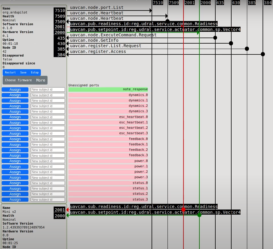
Alternatively, you can use Yukon. An example of monitor is shown below:

Step 3. Factory reset
A force reset of the firmware to default is recommended after every software update.
Next steps are expected that your firmware in the default state.
You can reset the registers by sending 2 commands:
- first
COMMAND_FACTORY_RESET=65532, - then
COMMAND_RESTART=65535.
Below is an example of how to send the commands using Yakut.

Alternatively, you can send them using Yukon.

TIP
The error after COMMAND_RESTART appeared because the node restarts immediately without replying. That's ok.
Step 4. Ports configuration
TIP
According to the specification (opens new window) the port IDs should be in the range [0, 6143]. Disabled subjects should have port id 65535.
A minimum possible application requires readiness and setpoint ports to be configured:

A fully configured application with auxillary ports crct.5v, crct.temp, crct.vin, feedback* can be as following:

Some parameters only take effect after a restart, so always save the registers and restart the node after making changes:

If Yukon commands don't work, you can always send them with Yakut:
y cmd 50 65530 # save registers
y cmd 50 65535 # restart the device
Step 5. Parameters configuration
Open the Registers window.
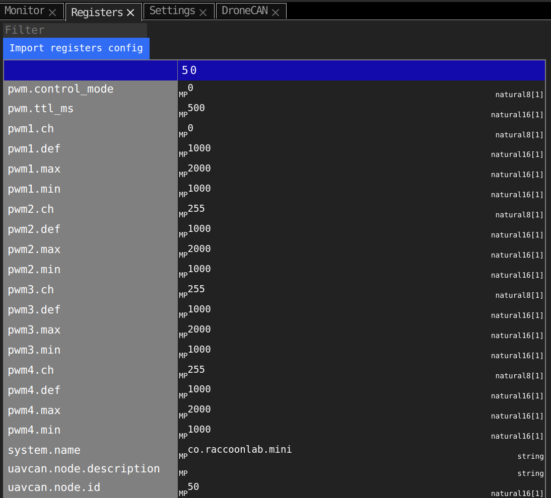
The following parameters must be configured via the register interface:
uavcan.node.id,pwm*registers,pwm.ttl_ms,
The value of uavcan.node.id register must be unique within the network. By default it is 50. It must be withing the range [1; 126].
The register value of pwm.ttl_ms must be at least twice more than the setpoint period!
The default value is 500 ms, that should be good for mist of the application.
Since right now the setpoint type is Vector31, pwm*.ch registers supports values from 0 to 30.
Other values will configure the corresponded pwm pin to the default state.
By default, pwm*.min=1000, pwm*.max=2000 and pwm*.def=1000 are configured for ESC For ESC.
If you use a servo, you are probably need to customize them.
TIP
Don't forget that pwm1 and pwm2 have 5V3, but pwm3 and pwm4 have RX pin instead.
In the end of the configuration it is necessary to save registers and restart the node.
Step 6. Control the node
Let's say, you have the following config:
pwm1.ch= 0,setpointport is 2000,readinessport is 2001,feedback1port is 2002.
and you have saved the registers and restarted the node as it was mentioned before.
You can create in Yukon setpoint and readiness publishers and feedback subscription and control the node as shown in the video below:
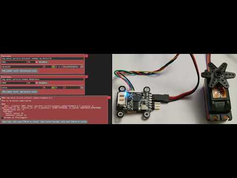
Please, pay attention on the following details of how the node works.
Readinesscommand controls the device mode. By default it is STANDBY where it doesn't react on any input setpoint. You should explicetly set ENGAGED mode. If a node doesn't receive this message forttl_msmilliseconds, it goes back to the STANDBY mode. In STANDBY mode node blinks with BLUE color, in ENGAGED mode it has solid BLUE color.Setpointcommand has an effect only if the device is ENGAGED. If a node doesn't receive setpoint forttl_msmilliseconds, by the safety reasons it goes to the default state.Feedbackis useful to diagnose the node state.
The described behaviour is based on UDRAL Electronic Speed Controller (ESC) service. Mode details: https://github.com/OpenCyphal/public_regulated_data_types (opens new window).
Alternatively you can control the node with Yakut CLI. Click here to show details.
Let's say, you have configured registers.
First terminal session. Configure the Yakut environment variables and start to periodically send the readiness message to engage the device. Try the following script. Specify NODE_ID as your actual node ID.
#!/bin/bash
NODE_ID=50

REGISTER_BASE=uavcan.sub.readiness
PORT_ID=$(y r $NODE_ID $REGISTER_BASE.id)
DATA_TYPE=$(y r $NODE_ID $REGISTER_BASE.type | tr -d '"')
y pub -T 0.1 $PORT_ID:$DATA_TYPE 3
Another terminal session. Configure the Yakut environment variables and start to periodically send the setpoint command. Try the following script. Specify NODE_ID as your actual node ID and VALUE as desired value of setpoint withing range [0.0, 1.0]:
#!/bin/bash
NODE_ID=50
VALUE=0.1

REGISTER_BASE=uavcan.sub.setpoint
PORT_ID=$(y r $NODE_ID $REGISTER_BASE.id)
DATA_TYPE=$(y r $NODE_ID $REGISTER_BASE.type | tr -d '"')
y pub -T 0.05 $PORT_ID:$DATA_TYPE "[$VALUE, $VALUE, $VALUE, $VALUE]"
# 4.4. Ardupilot integration
WARNING
Ardupilot doesn't officially support Cyphal (at the time of writing), so it is expected to use the custom cyphal branch of ardupilot (opens new window), since PR is not merged.
1. Port configuration
The following Ardupilot Cyphal registers should have the same port identifiers as GPS:
| Port | Type |
|---|---|
| setpoint | reg.udral.service.actuator.common.sp/* (opens new window) |
| readiness | reg.udral.service.common.Readiness.0.1 (opens new window) |
2. Channels configuration
3. Verification
# 4.5. PX4 integration
WARNING
At the moment:
- PX4 sends setpoint within the range [0; 8192]. So, you either need to configure
control_moderegister as 1 or to switch into a custom branch with fixed scaling. The fix was proposed in the PR #21475 (opens new window). This PR also divides ESC.0 topic into 2 for setpoint and readiness. - It is only avaliable on fmu-v5.
- Anyway, PX4 Cyphal support is a "work in progress".
PX4 sends setpoint and readiness with following values:
- setpoint port ID is
uavcan.pub.esc.0.id, - readiness port ID is
uavcan.pub.esc.0.id+ 1.
These port identifiers of the autopilot should be the same as those of the node.
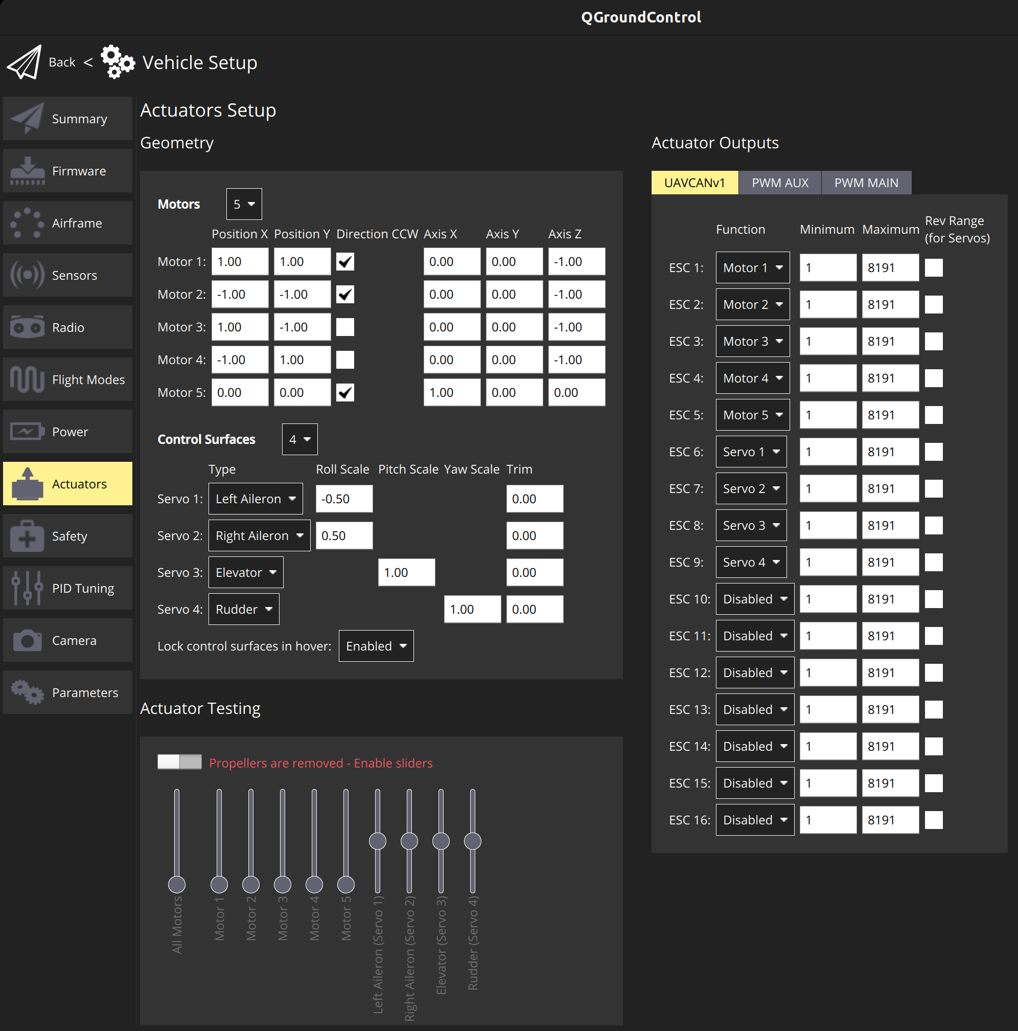
It is recommended to verify the setup with Actuator Testing panel. Below you can see a Cyphal VTOL example on a custom PX4 v1.14 firmware:
# 4.6. Versions
Micro and mini v2 releases:
| Version | Description |
|---|---|
| v1.5.10_112f1595 (opens new window) Nov 17, 2023 | Improvements: - Improve feedback: it sended last received readiness state instead of the actual one - Use Vector31 instead of Vector4 - Update default name and add HW version - Add IWDG Fixes: - Fix PWM2-PWM3 doesn't work issue (opens new window) - Fix RGB LED - Minor standard related fixes |
| v1.4.0_52df65ce (opens new window) Jun 19, 2023 | - Fix port.List issue - Add diagnostic.Record - Fix default name - Few other fixes |
| v1.2_b4e042b (opens new window) Feb 23, 2023 | - Add port.List - Add hardware version - Extend git hash length to 64 bit - Few other fixes |
| v1.1.2_4f393f4 Nov 17, 2022 | Add control mode parameter to be compatible with PX4 |
| v1.0.1_47a71fd (opens new window) Oct 23, 2022 | Initial release |