# 5. DroneCAN PWM node
This page is about DroneCAN software related details such as interface, supported features, parameters, configuration and usage example and versions history. For general information please refer 1. General, for hardware related details including connection example scheme please refer 2. uNode or 4. Mini v2 node.
This section is related to the latest released version of the software.
# 5.1. DroneCAN interface
This node interacts with the following messages:
| № | type | message |
|---|---|---|
| 1 | subscriber | uavcan.equipment.esc.RawCommand (opens new window) |
| 2 | subscriber | uavcan.equipment.actuator.ArrayCommand (opens new window) |
| 3 | publisher | uavcan.equipment.esc.Status (opens new window) |
| 4 | publisher | uavcan.equipment.power.CircuitStatus (opens new window) |
| 5 | publisher | uavcan.protocol.debug.LogMessage (opens new window) |
| 6 | publisher | uavcan.equipment.device.Temperature (opens new window) |
Besides required and highly recommended functions such as NodeStatus (opens new window) and GetNodeInfo (opens new window) this node also supports the following application-level functions:
| № | type | message |
|---|---|---|
| 1 | RPC-service | uavcan.protocol.param (opens new window) |
| 2 | RPC-service | uavcan.protocol.RestartNode (opens new window) |
| 3 | RPC-service | uavcan.protocol.GetTransportStats (opens new window) |
5.1.1. Circuit status
PWM-node as well as any other our nodes measures and sends 5V and Vin voltages as 2 uavcan.equipment.power.CircuitStatus (opens new window) messages
The first message has circuit_id=NODE_ID*10 + 0 and following 3 significant fields:
- voltage - is the 5V voltage
- current - is the max current for the last 0.5 seconds (supported only by
5Anode) - error_flags - might have ERROR_FLAG_OVERVOLTAGE or ERROR_FLAG_UNDERVOLTAGE or non of them
The second message has circuit_id=NODE_ID*10 + 1 and following 3 significant fields:
- voltage - is the Vin voltage
- current - is the average current for the last 0.5 seconds (supported only by
5Anode) - error_flags - ERROR_FLAG_UNDERVOLTAGE or non of them. There is no ERROR_FLAG_OVERVOLTAGE flag because the expected max Vin voltage is unknown.
5.1.2. Device temperature
The node measures and sends device temperature as uavcan.equipment.device.Temperature (opens new window) message.
5.1.3 Log messages
The node may inform you with a text message when something happen. It uses uavcan.protocol.debug.LogMessage (opens new window) message.
A visualization of this message in gui_tool in case of error shown on a picture below.

This message might be used in PX4 as logmessage (opens new window) feature.
5.1.4 Esc Status
If you use Tmotor ESC Flame 80 A (opens new window) it might be possible to get feedback from it via UART port. On the image below you can see an example of connection scheme. Here pwm.4_ch is configured on a particular channel and pwm.fb_2_type = 1 (esc flame mode).

If you use Tmotor ESC Thunder 300 A (opens new window) it might be possible to get feedback from it via UART port. Here the mini node is connected to a single ESC Thunder and configured as RawCommand channel 0. A second ESC Thunder can be connected as well.

Tmotor ESC Alpha 180 A (opens new window) is supported as well. On the image below you can see an example of connection scheme. Here pwm.1_ch is configured on a particular channel and pwm.fb_1_type = 3 (esc alpha mode).

In this case, the PWM node will send uavcan.equipment.esc.Status (opens new window) for each of up to 2 activated channels.
It will fill the following fields of the message:
| № | Field name | Description |
|---|---|---|
| 1 | error_count | This field is used for debug only. The value is incremented after receiving of each byte. If it doesn't change, typically your UART connection is broken. |
| 2 | voltage | Voltage on the regulator, volt. |
| 3 | current | Current, ampere. |
| 4 | temperature | Temperature, kelvin. |
| 5 | rpm | Rotation per minute. |
| 4 | esc_index | Index of esc. From 0 to 31. |
This feature is supported only by mini v2 node. micro node doesn't support this feature.
Since ESC regulator doesn't now about the number of poles, you typically need to set the correponded value with
mot_num_polesparameter.
# 5.2. DroneCAN Parameters
Below you can see the table with complete set of the node parameters.
The actual list of parameters on your node depends on the firmware version and hardware type.
| № | Parameter name | Note | Description |
|---|---|---|---|
| 0 | uavcan.node.id | Reboot required | Node identifier |
| 1 | stats.flight_time_sec | The total flight time in seconds. Appeared since v0.5.2 | |
| 2 | pwm.cmd_type | Reboot required | 0 means RawCommand, 1 means ArrayCommand. Appeared since v0.5.2 |
| 3 | pwm.frequency | Reboot required | Pwm frequency from 50 to 400 Hz. Appeared since v0.8.8 |
| 4 | pwm.*_ch | Index of setpoint channel. -1 means disabled, -2 means GPIO SET. | |
| 5 | pwm.*_min | PWM duration when setpoint is min. | |
| 6 | pwm.*_max | PWM duration when setpoint is max. | |
| 7 | pwm.*_def | PWM duration when setpoint is negative or there is no setpoint at all. | |
| 8 | pwm.mot_num_poles | Motor number of poles. Appeared since v0.9.8 | |
| 9 | pwm.fb_*_type | ESC feedback type (fb1 ~ pwm3, fb2 ~ pwm4): - 0 - disabled (by default), - 1 - ESC Flame, - 2 - ESC Thunder(since v0.12), - 3 - ESC Alpha (since v0.13), - 4-9 - reserved, - 10+ - forward mode with custom UART baudrate (since v0.12). | |
| 10 | enable_5v_check | Set ERROR status if 5V voltage is out of range 4.5 - 5.5 V | |
| 11 | enable_vin_check | Set ERROR status if Vin voltage is less than 4.5 V | |
| 12 | cmd_ttl_ms | Time to live (opens new window) timeout | |
| 13 | system.can_bus_check_level | Every CAN bus error will be treated as a specified level of error. Appeared since v0.9.8 | |
| 14 | system.log_level | Reboot required | Specify what level of log can be sent. Appeared since v0.5.2 |
| 15 | uavcan.node.name | Reboot required | Name of the node |
The detailed description of some of these parameters is shown in the chapters below.
5.2.1. Log level
According to the LogLevel (opens new window) message, we have 4 log levels:
- debug
- info
- warning
- errors
log_level parameter might have values described in the table below.
| Param value | DEBUG | INFO | WARNING | ERROR | Description |
|---|---|---|---|---|---|
| 0 | + | + | + | + | Log everything |
| 1 | - | + | + | + | At least INFO level |
| 2 | - | - | + | + | At least WARNING level |
| 3 | - | - | - | + | At least ERROR level |
| 4 | - | - | - | - | Disable logging |
0 - log everything, 1 - discard less than info level, 2 - discard less than warn level, 3 -log only errors, 4 - disable logging
5.2.2. Mapping configuration
Mainly parameters are dedicated to PWM mapping configuration. Here we have 2 or 4 groups so called pwm1, pwm2, pwm3, pwm4 of the parameters.
Old versions of the software may have different naming of these groups:
A1,A2,B1,B2.
Below you can see a table with their description:
| Param name | Description |
|---|---|
| pwm*_ch | Index of setpoint channel (RawCommand or ArrayCommand). Default value -1 means disable. |
| pwm*_min | PWM duration when setpoint is min (RawCommand is 0 or Command is 0.0) |
| pwm*_max | PWM duration when setpoint is max (RawCommand is 8191 or Command is 1.0) |
| pwm*_def | PWM duration when setpoint is negative or there is no setpoint at all |
5.2.3. Node health checks
The node performs self testing and change his health if something goes unexpected. But sometimes warnings and errors might be annoying, so here you have 3 option to disable some of them.
enable_5v_checkchecks 5V node's voltage. If the 5V check is enabled (the parameter value is 1), the node state will beERRORif the 5V voltage is less than 4.5V or bigger than 5.5Venable_vin_checkchecks checks node's Vin voltage. Right now it doesn't supported and this check is always disabled.can_bus_check_levelspecifies at which level every CAN bus error will be treated. If the parameter value is 0, the node will ignore all CAN bus errors. If the parameter value is 1 or 2, the node will keep WARNING or ERROR state for 6 seconds.
5.2.4. Node name customization
If custom node name is not specified, the node name will be defined with the software name: mini v2 node has name mini_v2, micro node name is micro.
You can set the custom node name. It will allow you easier to distinguish different types of nodes. For example, you can set names left_aileron, elevators, forward_left_esc, etc. You need to set name parameter, save parameters and reboot the node.
A few rules:
- The name should be human-readable non-empty ASCII string. An empty name is not permitted.
- The name can't be changed while the node is running. You need to reboot the node to update the name.
- Allowed characters are: a-z (lowercase ASCII letters) 0-9 (decimal digits) . (dot) - (dash) _ (underscore).
# 5.3. Getting started (bench test)
Before mounting on a real vehicle, especially when using the node for the first time, it is recommended to test the node and perform configuration on a bench using gui_tool:
- On Linux use the latest dronecan/gui_tool (opens new window),
- On Windows consider to use OpenCyphal-Garage/gui_tool (opens new window).
The following checklist allows you to test most of the features and configure the most important parameters.
Step 1. Connect the node properly to a sniffer. Initially, when there is no command, the node goes into STANDBY mode and LED should blink with blue color
The simplest connection scheme just for bench testing and configuration is shown below.
 Fig. uNode connected to a servo and a sniffer without an input command
 Fig. mini v2 connected to a servo and a sniffer without an input command
Here, the node is connected with 2 devices:
- a CAN sniffer via CAN (the sniffer is connected to PC via USB and power the node),
- a servo is connected via pwm1 channel.
For other connection schemes, e.g. with ESC and motor, please refer to the hardware page of the corresponding board.
Initially, without any input commands, the node should blink with blue color, which means that the node is in STANDBY state. If the node blinks with Yellow and even Red color it means that the node has a warning or error. You can try to get more info in gui tool. For better understanding of the color, please refer to the LED Meaning page.
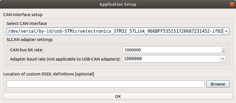
Step 2.1. Open gui_tool and set baudrate to 1000000
Step 2.2. Set the local node ID. The node should send data and respond to GetNodeInfo
Apply the Local Node ID by clicking the button in the corresponding field at the top. Check that the node publishes some data like NodeStatus and GetNodeInfo. You can quickly press 2 times on the node in Online nodes list. You should be able to see additional information such as node name, software version, UID, etc.

The node should respond with the software version that suits you (probably it should be the latest available stable version).
If your node doesn't send
GetNodeInfoit probably means that your gui_tool is still in anonymous mode. Apply local node ID.
Step 3. Configure the node ID and name, Store parameters, then reboot it. ID value and name should be updated.
Select the node ID by changing uavcan.node.id that fits your CAN-network without ID-collision.
The name is optional thing. It should help you to identify it among other similar nodes. Change it by typeing new name in name parameter.
Step 4. Check CircuitStatus. The node should measure the input voltages and temperature correctly.
Use Tools > Subscriber to look at topics.


If you power a node from USB, the voltage should be ~5V.
The temperature may be a slightly higher than in your room.
Step 5. Configure command_type, pwm_frequency, pwm* and press the reboot button. The node should correctly control a device (servo or ESC) with either Esc or Actuator Panel.
If the parameters are configured correctly, you can control a servo by moving the sliders. An example with Actuator Panel is shown below:
 |  |
If the node successfully receives the setpoint, it will go into the ENGAGED state, so its internal RGB LED will be solid blue.
After the configuration, don't forget to
Store Allparameters and reboot the node.
Step 6. Configure the pwm.mot_num_poles, pwm.fb_1_type and pwm.fb_2_type parameters if you use ESC. The node should return EscStatus correctly.
You need this step only if you use mini v2 node and want to get a feedback from ESC Flame, ESC Thunder or ESC Alpha.
To enable a specific feedback type, you should set the corresponded value to pwm.fb_*_type parameters. At that moment a node expect that both paramaters are configured in the same mode:
pwm.fb_1_typeis theRXpin betweenPWM3andGND,pwm.fb_2_typeis theRXpin betweenPWM4andGND.
If you use ESC Flame, set both paramters value to 1.
If you use ESC Thunder, set both paramters value to 2. You additionally need to set pwm.3_ch and pwm.4_ch to -2 to configure them as GPIO SET (3.3 V).
If you use ESC Alpha, set both paramters value to 3.
Otherwise, set these paramters to 0.
Since an ESC doesn't know about number of motors poles, yuo should specify the correct number into pwm.mot_num_poles paramter.
You can check this using ESC Panel and Tools > Subscriber.
Step 7. Configure the cmd_ttl_ms parameter. When you close the ESC or Actuator Panel, the node will go to STANDBY mode after the specified period of time, where all PWM channels should have the default values.
This is a safety feature. You typically don't want a motor to continue spinning if your autopilot fails or the CAN-wire is broken.
Step 8. Configure log_level. If it is not the default, the node should report about TTL timeout event in Log messages.
You can play with log_level to get the notification level you need for your logging system. By default, the node notifies only about real critical events.
Step 9. Check the flight_time_sec parameter. After the node goes to STANDBY state, it should increment the flight_time_sec parameter value within a short time .
Typically, you should set this parameter to 0 before mounting the node in a vehicle, but it is up to you.
Step 10. Specify the strictness of onboard checks.
The current list of checks that you are able to modify are: enable_5v_check, enable_vin_check, can_bus_check_level and log_level.
Some more checks might be appeared in the future.
# 5.4. PX4 integration
It is recommended to use PX4 v1.13 or newer with Control Allocation (opens new window).
You can integrate this node with PX4 by performing the following steps:
- Choose the direred airframe and reboot the vehicle
- According to the PX4 user guide (opens new window) you need to set
UAVCAN_ENABLEparameter to3value and reboot the autopilot - Configure Actuators and test them. Check the official instruction (opens new window) for details.
PX4 v1.14 sends 2 commands: esc.RawCommand for ESC (values from 0 to 8191) and actuator.ArrayCommand for control surfaces (values from -1.0 to 1.0).
An examples of the DroneCAN configuration for specific vehicles will appear here soon:
- PX4 Small quadcopter example
- PX4 X-UAV Mini Talon example
PX4 Generic quad delta VTOL example- PX4 VTOL example
# 5.5. Software versions
History of all releases and changes related to the node:
| Version | Date | Description |
|---|---|---|
| v0.13.0 27d18a2 (opens new window) | Aug 23, 2023 | - Add ESC Alpha |
| v0.12.2 0601cb2 (opens new window) | Aug 09, 2023 | - Fix ESC Thunder RPM scaling. |
| v0.12.0 41023e0 (opens new window) | Jul 25, 2023 | - Add ESC Thunder feedback support and feedback forwarder mode. - Fix ArrayCommand range (it was from 0.0 to 1.0, now it is from -1.0 to 1.0) - Add meaningful default node name (it was unknown by default) |
| v0.10.17 3960cc2 (opens new window) | Mar 29, 2023 | - Fix bug with cmd_ttl_ms - Send ESC feedback only when it is availiable, not with a fixed period - Update names of the most of parameters |
| v0.9.10 9fe8120 | Dec 10, 2022 | Bug found: cmd_ttl_ms doesn't work. Do not use this version of the firmware. - Add mot_num_poles - Add parameters to disable esc_status - Update internal LED standard for all v2 hardware - Add can_bus_check_level |
| v0.8.8-stable f915a39 (opens new window) | Sep 14, 2022 | - Add Mini v2 and Micro boards - Add CAN-bus error status monitor - Add string name - Add temperature sensor - Add custom pwm frequency - Improve transport stats |
| v0.5.7 f951dc6 (opens new window) | May 06, 2022 | - Use individual TTL for each setpoint instead of a single one |
| v0.5.2.1 a208527 (opens new window) | Apr 5, 2022 | - Extended Mini v1 RC channels amount to 20, - Add ArrayCommand - Add LogMessages - Add Watchdog - Add Flight time recorder |
| v0.3.2.1 3aaaacf (opens new window) | Mar 28, 2022 | Mini v1 esc-flame with extended RC channels amount to 20 |
| v0.3.2 0b55576 (opens new window) | May 31, 2021 | Mini v1 esc-flame feedback first release |
| v0.3.0.1 699cbd6 (opens new window) | Mar 28, 2022 | Mini v1 (4 channels) with extended RC channels amount to 20 |
| v0.3.0 04866c1 (opens new window) | Apr 05, 2021 | Mini v1 (4 channels) first release |
Note that Mini v1 will not have further software updates. It is recommended to use mini v2 instead.