# 2. V2 GNSS (NEO-M8N) MAG BARO hardware [revision 2.3.2]
This page covers hardware-specific details of GNSS module witch also includes magnetometer and barometer. For general information, see 1. General, for software related details see Cyphal interface or DroneCAN interface.
| View | Top | Bot |
|---|---|---|
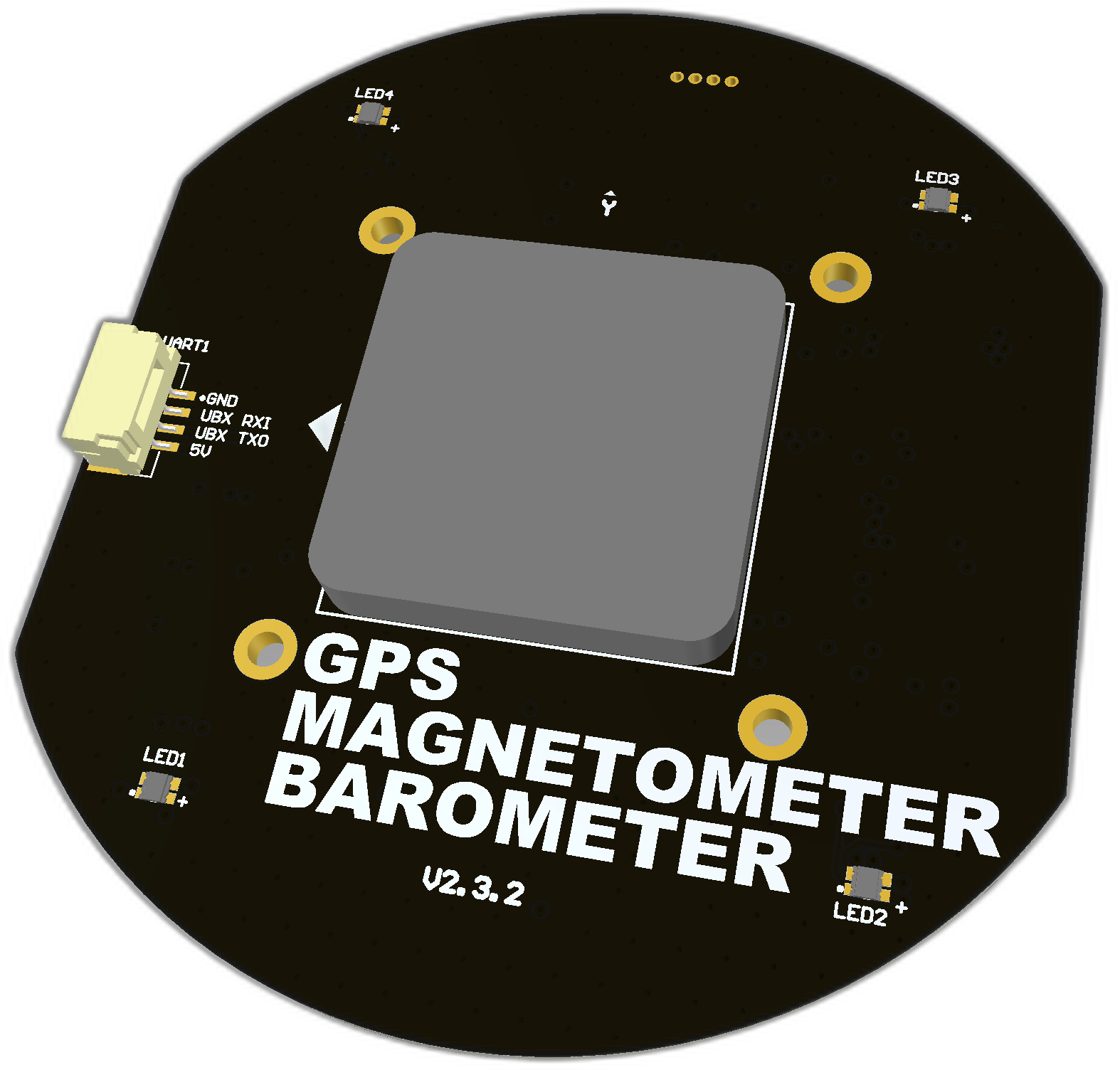 | 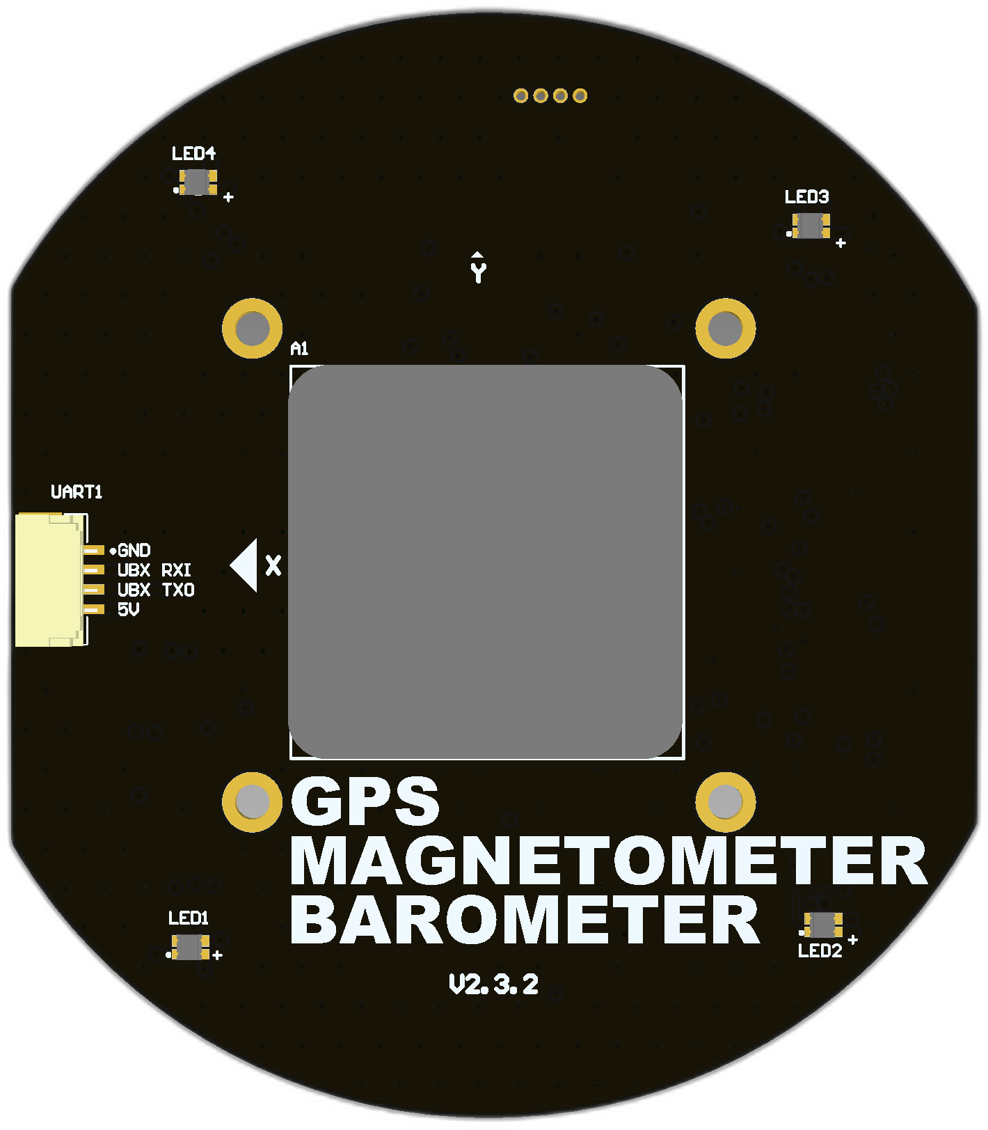 | 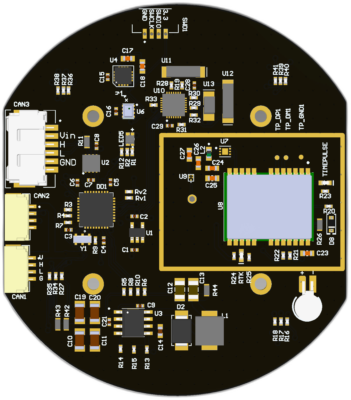 |
 | 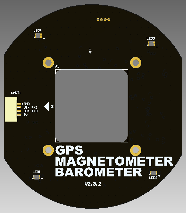 | 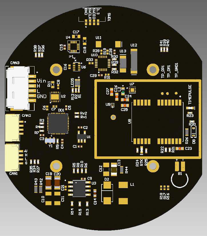 |
# 2.1. Features
- Concurrent reception of GPS, GLONASS, Galileo and BeiDou
- Centimeter-level accuracy in a small and energy-efficient module
- Easy integration
- Magnetometer RM3100 (opens new window)
- Baro BMP280 (opens new window)
- 2 JST SM04B connectors compatible with Dronecode Autopilot Connector Standard (opens new window)
- 1 MOLEX (opens new window) non standart connector
- GNSS module NEO-M8N (opens new window)
- RHCP Ceramic GPS Antenna (1461680001) (opens new window)
# 2.2 Wiring
Schematic features. Schematic can be provided via issue.
Connectors
The node has 3 connectors which are described in the table below.
| № | Connector | Description |
|---|---|---|
| 1 | CAN1, CAN2 | Devices that deliver power to the bus are required to provide 4.5–5.5 V on the bus power line, 5.0 V nominal. Devices that are powered from the bus should expect 4.5–5.5 V on the bus power line. The current shall not exceed 1 A per connector. |
| 2 | SWD | STM32 firmware updating using programmer-sniffer. |
| 3 | CAN3 | Can be powered from 5.5 to 30 volts and connected to CAN. |
| 4 | UART | Can be used to setup the GPS module |
Here (opens new window) you can find manufacturer part number of connectors it self and its mates.
Pin configuration and functions
| Pin | CAN3 | Pin | CAN1, CAN2 | SWD | UART |
|---|---|---|---|---|---|
| 1 | Vin | 1 | 5V in | GND | 5V |
| 2 | Vin | 2 | CAN High | SWCLK | TXO |
| 3 | CAN High | 3 | CAN Low | SWDIO | RXI |
| 4 | CAN Low | 4 | GND | 3.3V | GND |
| 5 | GND | ||||
| 6 | GND |
Here you can see all connections of MCU.

# 2.3. Specifications
Mechanical
Scheme is shown on the picture below. CAN model can be provided via email request or issue on github or downloaded on GrabCAD (opens new window).

| Width, mm | Length, mm | Height, mm | |
|---|---|---|---|
| Outline | 70 | 61.3 | 12.6 |
| PCB | 70 | 61.3 | 1.6 |
Total weight of device less than 50 g.
Housing
Information about case presented here.
Absolute Maximum Ratings
| Parameter | MIN | MAX | UNIT |
|---|---|---|---|
| Vin (CAN1) | 5.5 | 55* | V |
| V (CAN2, CAN3) | 4.5 | 5.5 | V |
| I max | A | ||
| Operating temperature |
*Noted Voltage should be delivered only with current limitation under 2.5 Amp.
Recommended operating conditions
| Parameter | Value | UNIT |
|---|---|---|
| Vin (CAN3) | 30 | V |
| V (CAN1, CAN2) | 5 | V |
| I max | A |
ESD ratings
| Description | Value | UNIT |
|---|---|---|
| Human-body model (HBM) | 2000 | V |
| Charged-device model (CDM) | 500 | V |
# 2.4. Integration
Recommended mechanical mounting

Connection example diagram

# 2.5. Power Supply Recommendations
Device is designed to operate from an input voltage supply range between 4.5 V and 5.5 V over CAN2 or CAN3 connector, or 5.5 - 30 V from CAN1. This input supply must be able to withstand the maximum input current and maintain a stable voltage. The resistance of the input supply rail should be low enough that an input current transient does not cause a high enough drop that can cause a false UVLO fault triggering and system reset. The amount of bulk capacitance is not critical, but a 47-μF or 100-μF electrolytic capacitor is a typical choice.
# 2.6. Revision history
| View | Version | Description |
|---|---|---|
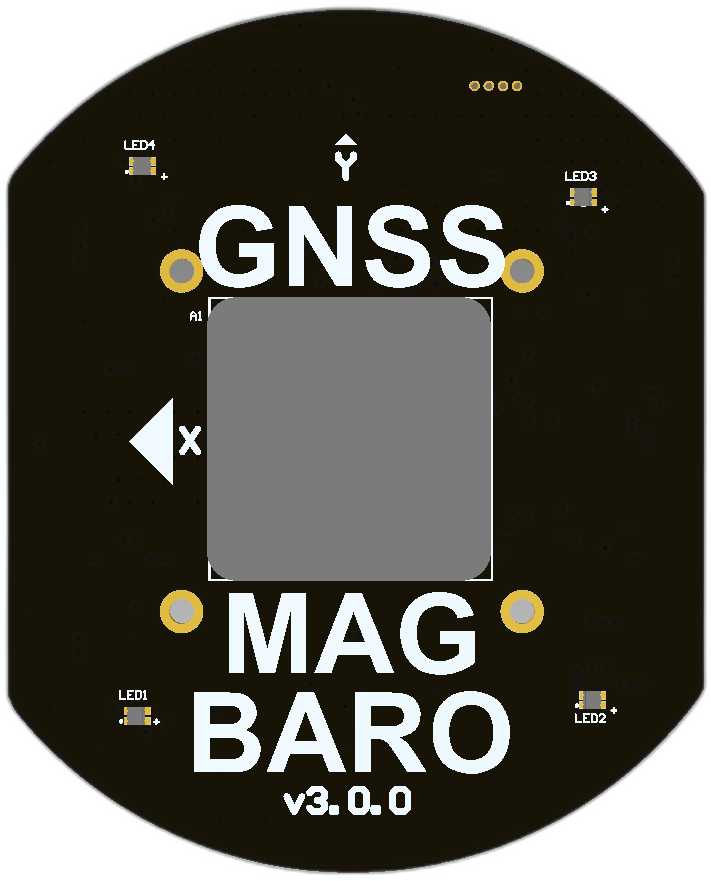 | v3.0.0 Summer, 2023 | The board is on the testing stage. - Migrate to stm32g0 from stm32f103 |
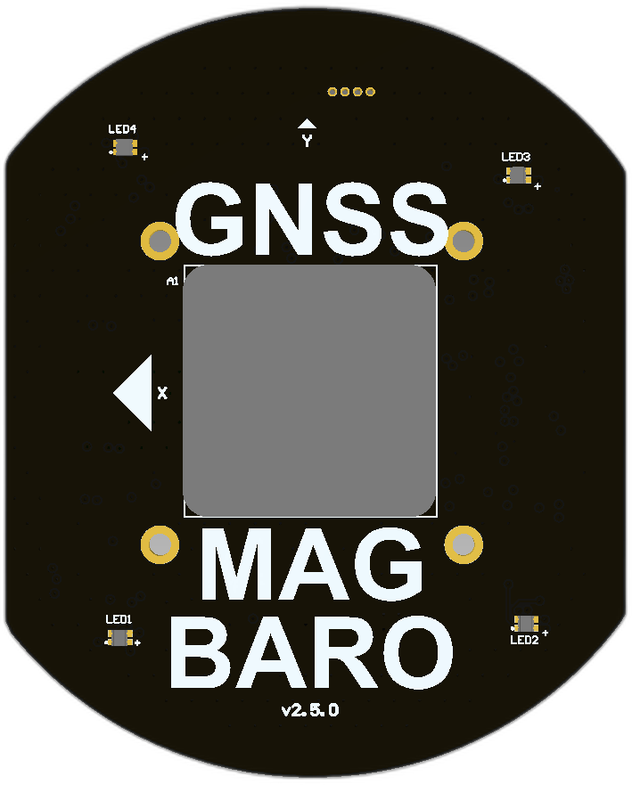 | v2.5.0 27 Mar, 2023 | The latest stable version. - Timepulse and EXTINT pin wired to connector CC and connected to MCU - Slightly increase the board size - Fix UART connector |
| v2.3.2 (opens new window) Oct 14, 2022 | The version of the board with a small bug on UART connector. It is not on production. - Integrate RM3100 in PCB - Assign SS pin to PA2 - Add UART connector with wrong pinout!!! - Use RGB LEDs instead of address LEDs |
| v2.3.0 Aug 10, 2021 | The first stable version. Do not use it in a new design. - Ingegrage RM3100 - Assign SS pin to PA4 (so RM3100 doesn't work on the lastest firmware) - Address LEDs (so they don't work on the lastest firmware) |