# 2. V2.5.0 GNSS (NEO-M8N) MAG BARO hardware
This page covers hardware-specific details of GNSS module witch also includes magnetometer and barometer. For general information, see 1. General, for software related details see Cyphal interface or DroneCAN interface.
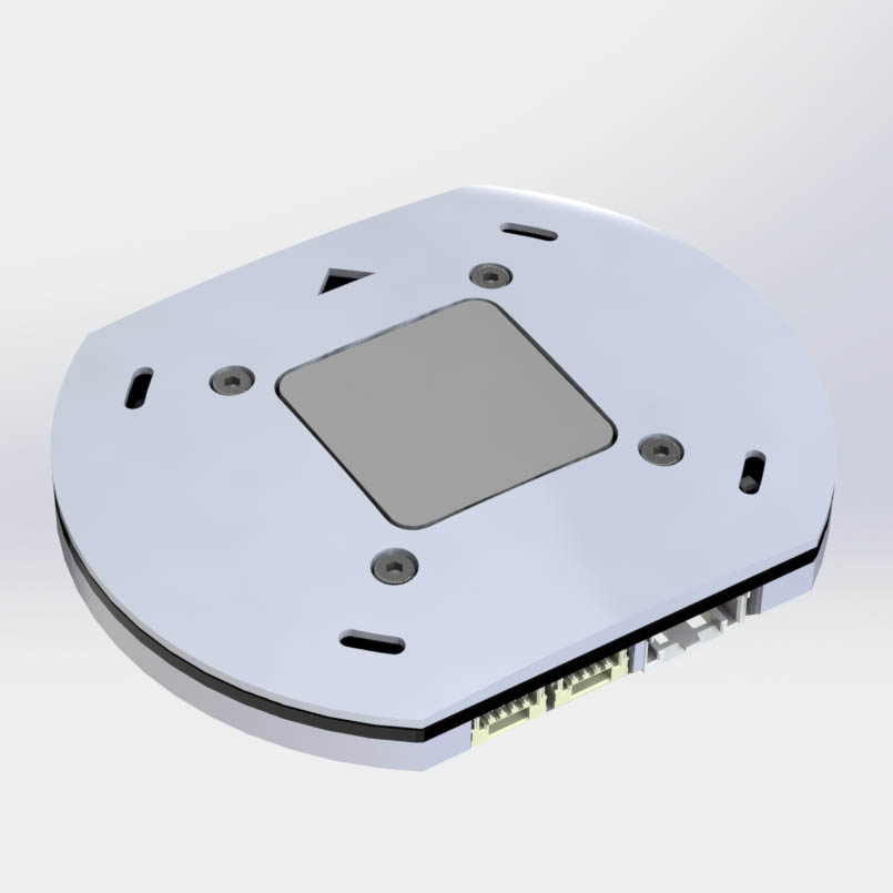
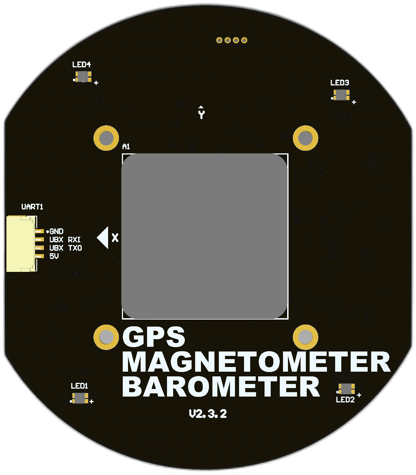
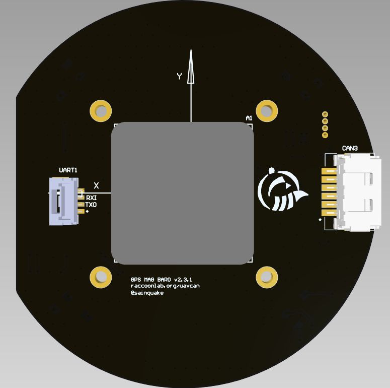
| View | Top | Bot |
|---|---|---|
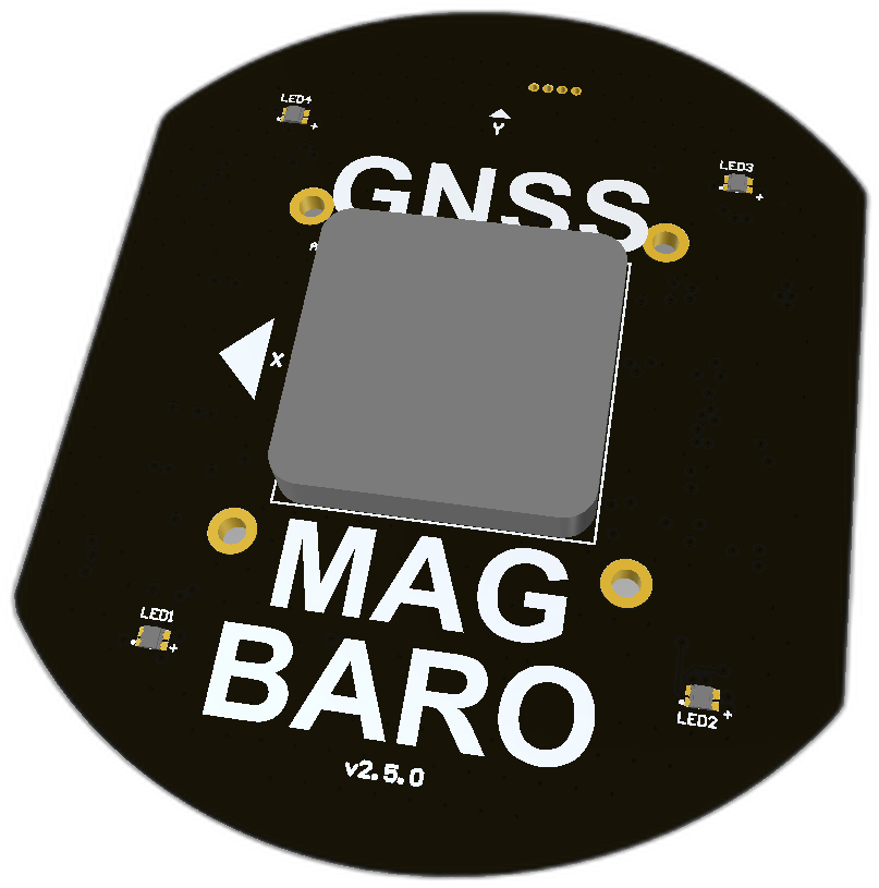 | 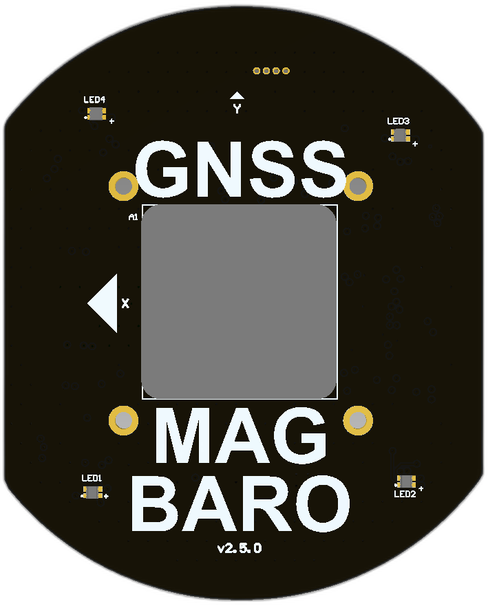 | 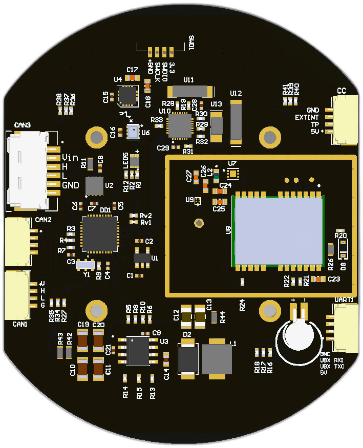 |
 | 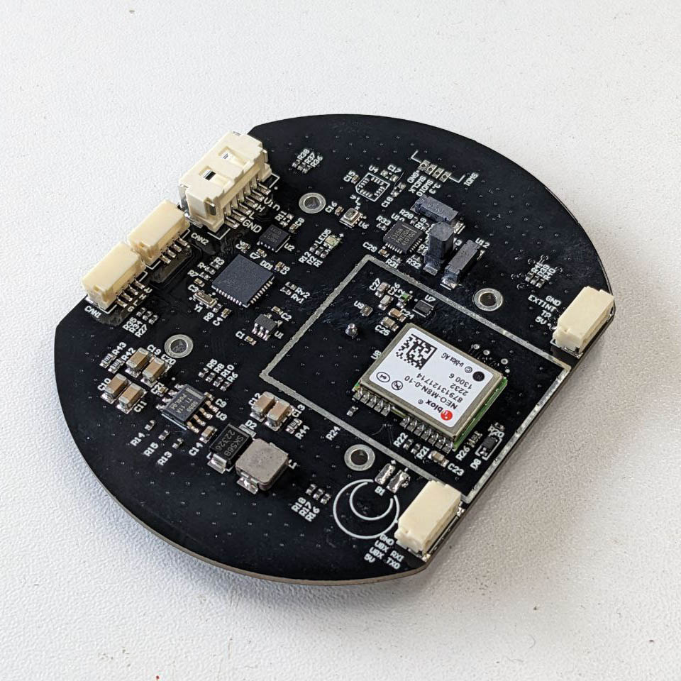 |
# 2.1. Features
- Concurrent reception of GPS, GLONASS, Galileo and BeiDou
- Centimeter-level accuracy in a small and energy-efficient module
- Easy integration
- Magnetometer RM3100 (opens new window)
- Baro BMP280 (opens new window)
- 2 JST SM04B connectors compatible with Dronecode Autopilot Connector Standard (opens new window)
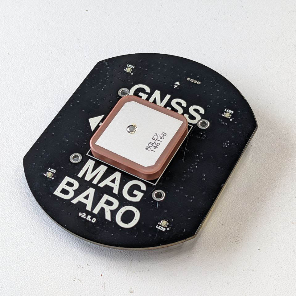
- 1 MOLEX (opens new window) non standart connector
- GNSS module NEO-M8N (opens new window)
- RHCP Ceramic GPS Antenna (1461680001) (opens new window)
# 2.2 Wire
Schematic features. Schematic can be provided via issue.
Connectors
The node has 3 connectors which are described in the table below.
| № | Connector | Description |
|---|---|---|
| 1 | CAN1, CAN2 | Devices that deliver power to the bus are required to provide 4.5–5.5 V (limited by TJA1042 (opens new window) driver operating voltage) on the bus power line, 5.0 V nominal. Devices that are powered from the bus should expect 4.5–5.5 V on the bus power line. The current shall not exceed 1 A per connector. |
| 2 | SWD | STM32 firmware updating using programmer-sniffer. |
| 3 | CAN3 | Can be powered from 5.5 to 30 volts and connected to CAN. |
| 4 | UART | Can be used to setup the GPS module |
| 5 | CC | Camera capture port can be used to receive external interrupt from camera trigger and send timepulse to payload such as autopilot |
Here (opens new window) you can find manufacturer part number of connectors it self and its mates.
Pin configuration and functions
| Pin | CAN3 | Pin | CAN1, CAN2 | SWD | UART | CC |
|---|---|---|---|---|---|---|
| 1 | Vin | 1 | 5V in | GND | 5V | 3.3V |
| 2 | Vin | 2 | CAN High | SWCLK | UBX_TXO | TIMEPULSE |
| 3 | CAN High | 3 | CAN Low | SWDIO | UBX_RXI | EXTINT |
| 4 | CAN Low | 4 | GND | 3.3V | GND | GND |
| 5 | GND | |||||
| 6 | GND |
Here you can see all connections of MCU.

# 2.3. Specifications
# Mechanical
Scheme is shown on the picture below. CAN model can be provided via email request or issue on github or downloaded on GrabCAD (opens new window).

| Width, mm | Length, mm | Height, mm | |
|---|---|---|---|
| Outline | 76 | 61.3 | 12.3 |
| PCB | 76 | 61.3 | 1.6 |
Total weight of device less than XX g.
# Housing
The casing can be downloaded from GrabCAD (opens new window) and printed in ABS or PLA plastic. The housing consists of two parts: top and bottom. It can be assembled using M2 L=6-8mm (opens new window) screws DIN 912 (ISO 4762) and Bras Hot Melt Insert Nut (opens new window). The assembled unit can be fixed with double-sided tape or with M2 L=12-20mm (opens new window) screws.
Bill of materials:
| Name | Qty | Comment |
|---|---|---|
| ABS or PLA plastic | ||
| M2 L=6-8mm (opens new window) screws DIN 912 (ISO 4762) | 4 | In case of double-sided tape mount type |
| Bras Hot Melt Insert Nut (opens new window) | 4 | |
| Double-sided tape | ||
| M2 L=12-20mm (opens new window) screws DIN 912 (ISO 4762) | 4 | In case of screws |
# GNSS Frequency filtering
The GNSS signal reception path consists of:
| Name | Part Number (Datasheet) |
|---|---|
| Antenna | Molex 2042860001 (opens new window) |
| SAW Filter | TDK B39162B4348P810 (opens new window) |
| LNA | Infineon BGA524N6E6327XTSA1 (opens new window) |
It provides reception, filtering and amplification in the desired frequency range. The satellite signal ranges and bandwidths of the device elements are schematically shown below.

Thus, it can be clearly seen that the device captures the entire upper frequency range of GNSS.
# Absolute Maximum Ratings
| Parameter | MIN | MAX | UNIT |
|---|---|---|---|
| Vin (HV) | 5.5 | 55* | V |
| V (LV) | 4.5 | 5.5 | V |
| I max | 1.0 | A | |
| Operating temperature |
*Noted Voltage should be delivered only with current limitation under 2.5 Amp.
# Recommended operating conditions
| Parameter | Value | UNIT |
|---|---|---|
| Vin (HV) | 30 | V |
| V (LV) | 5 | V |
| I max | A |
# ESD ratings
| Description | Value | UNIT |
|---|---|---|
| Human-body model (HBM) | 2000 | V |
| Charged-device model (CDM) | 500 | V |
# 2.4. Integration
Recommended mechanical mounting
Antenna sensitivity is highly dependent on the surrounding environment. Ensure that the antenna is not covered by any conductive material (e.g. carbon fibre) and is located on the top of the vehicle. The antenna should be able to pick up signals from the sky.
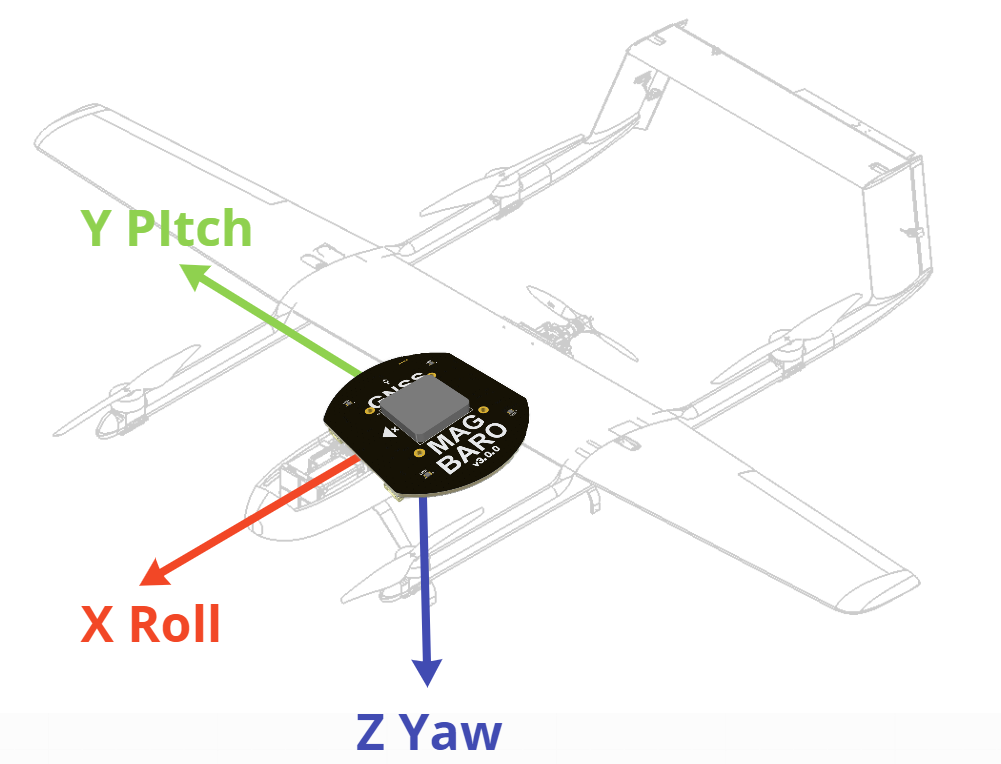
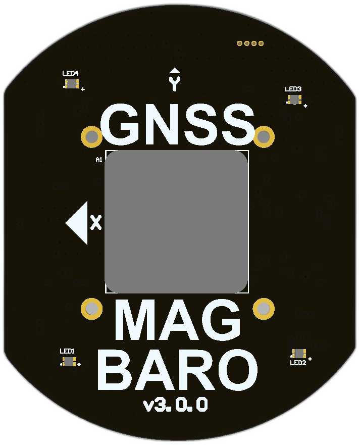
Once the magnetometer is used, it is necessary to mount the device in the right way. The typical way to mount it is shown in the picture below.
Connection example diagram
Device can be connected as termination in CAN bus, but in this case resistor R11 (0603, 120 Ohm) sould be plased on PCB.

Typically, the device can be connected directly to standard CAN bus using the CAN3 and CAN2 LV connectors, but it is better to connect using the CAN1 HV connector, as this connection type avoids power supply problems.

# 2.5. Power Supply Recommendations
Device is designed to operate from an input voltage supply range between 4.5 V and 5.5 V over CAN2 or CAN3 connector, or 5.5 - 30 V from CAN1. This input supply must be able to withstand the maximum input current and maintain a stable voltage. The resistance of the input supply rail should be low enough that an input current transient does not cause a high enough drop that can cause a false UVLO fault triggering and system reset. The amount of bulk capacitance is not critical, but a 47-μF or 100-μF electrolytic capacitor is a typical choice.
# 2.6. Revision history
| View | Version | Description |
|---|---|---|
 | v3.0.0 Summer, 2023 | The board is on the testing stage. - Migrate to stm32g0 from stm32f103 |
| v2.5.0 27 Mar, 2023 | The latest stable version. - Timepulse and EXTINT pin wired to connector CC and connected to MCU - Slightly increase the board size - Fix UART connector |
 | v2.3.2 Oct 14, 2022 | The version of the board with a small bug on UART connector. It is not on production. - Integrate RM3100 in PCB - Assign SS pin to PA2 - Add UART connector with wrong pinout!!! - Use RGB LEDs instead of address LEDs |
 | v2.3.1 | |
| v2.3.0 Aug 10, 2021 | The first stable version. Do not use it in a new design. - Ingegrage RM3100 - Assign SS pin to PA4 (so RM3100 doesn't work on the lastest firmware) - Address LEDs (so they don't work on the lastest firmware) |