# 6. DroneCAN interface
This page is about DroneCAN related details such as interface, supported features, parameters, configuration, usage examples and software versions. For general information, refer to the 1. General page, for hardware related details including connection example scheme please refer to the Hardware page:
This section is related to the latest released version of the software.
# 6.1. DroneCAN interface
This node interacts with the following messages:
| № | Type | Message | Rate |
|---|---|---|---|
| 1 | publisher | uavcan.equipment.gnss.Fix2 (opens new window) | 5-10 Hz |
| 2 | publisher | uavcan.equipment.air_data.StaticPressure (opens new window) | |
| 3 | publisher | uavcan.equipment.air_data.StaticTemperature (opens new window) | |
| 4 | publisher | uavcan.equipment.ahrs.MagneticFieldStrength (opens new window) | |
| 5 | publisher | uavcan.equipment.power.CircuitStatus (opens new window) | |
| 6 | publisher | uavcan.protocol.debug.LogMessage (opens new window) |
Besides required and highly recommended functions such as NodeStatus and GetNodeInfo this node also supports the following application-level functions:
| № | type | message |
|---|---|---|
| 1 | RPC-service | uavcan.protocol.param (opens new window) |
| 2 | RPC-service | uavcan.protocol.RestartNode (opens new window) |
| 3 | RPC-service | uavcan.protocol.GetTransportStats (opens new window) |
6.1.1. GNSS
It communicates with the GNSS module via UART and publishes uavcan.equipment.gnss.Fix2 (opens new window). Below you can see an example of the this message.
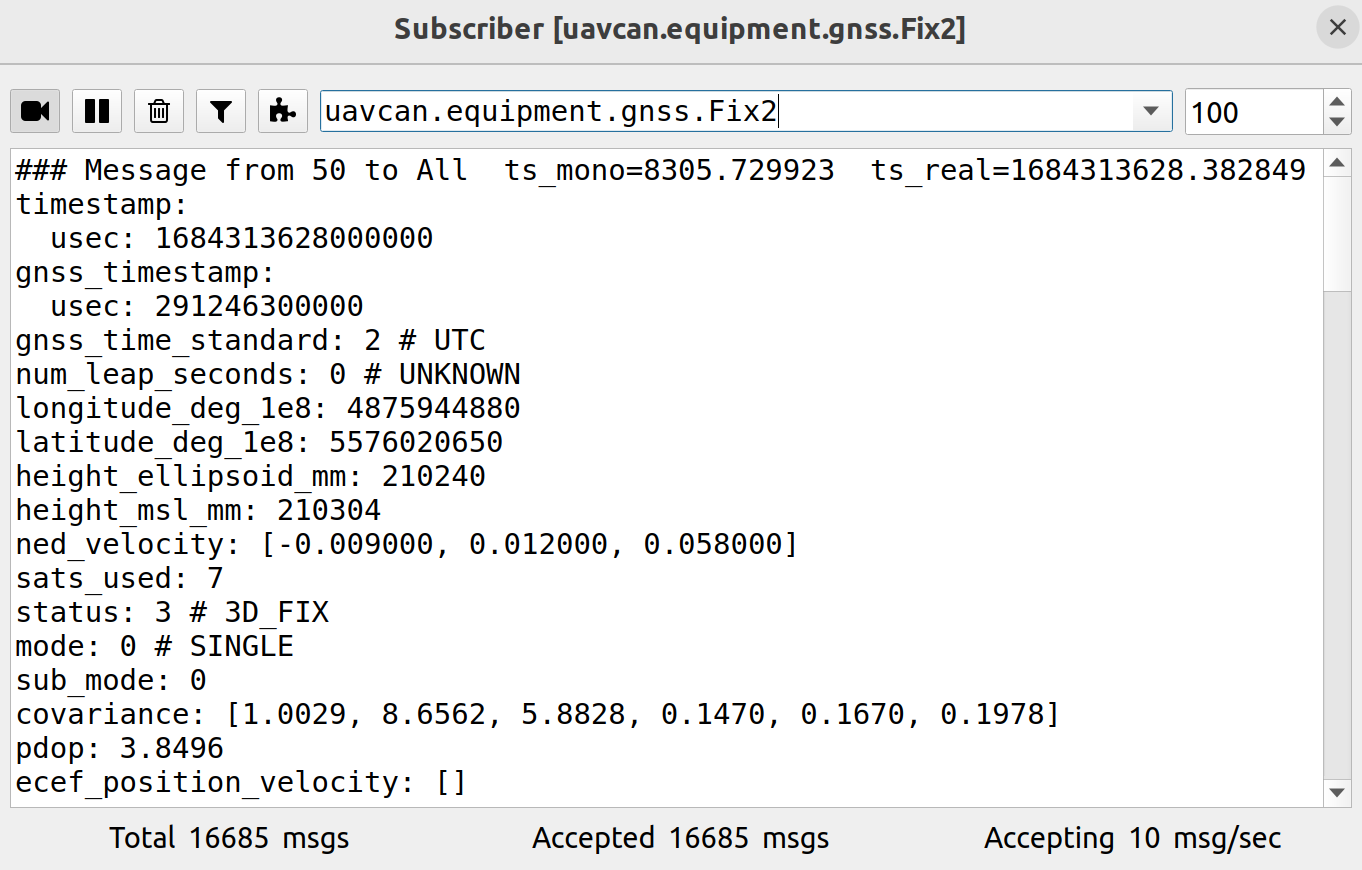
Here the message mostly corresponds NavPvt package.
Covariance is based on NavCov package. It is Diagonal matrix (first 3 fields corresponds to the position, last 3 fields corresponds to the velocity).
The field ecef_position_velocity is unused.
6.1.2. Barometer
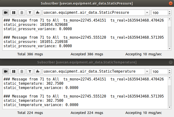
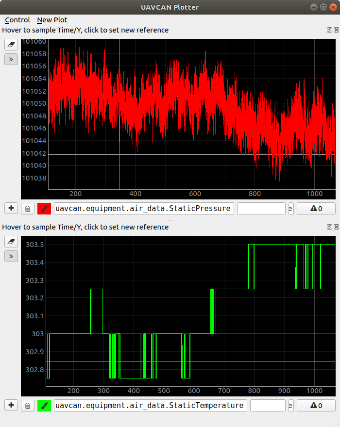
It publishes 2 messages:
- uavcan.equipment.air_data.StaticPressure (opens new window)
- uavcan.equipment.air_data.StaticTemperature (opens new window)
6.1.3. Magnetometer
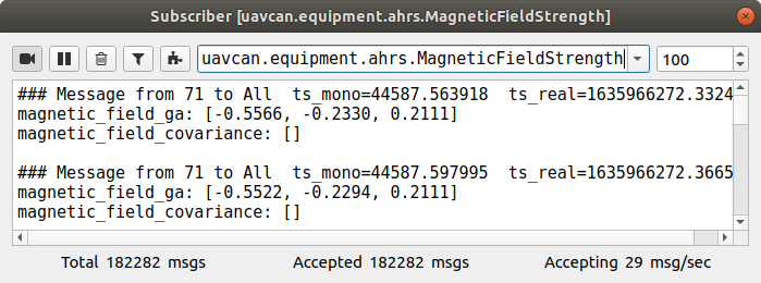
Both magnetometers publish uavcan.equipment.ahrs.MagneticFieldStrength (opens new window).
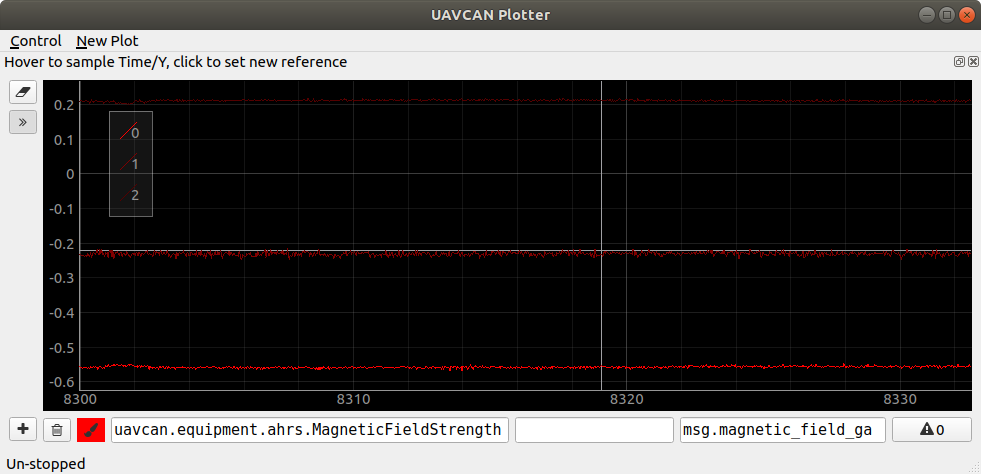
Below you may see an example of HMC5883L magnetometer raw data.
6.1.4. Circuit status
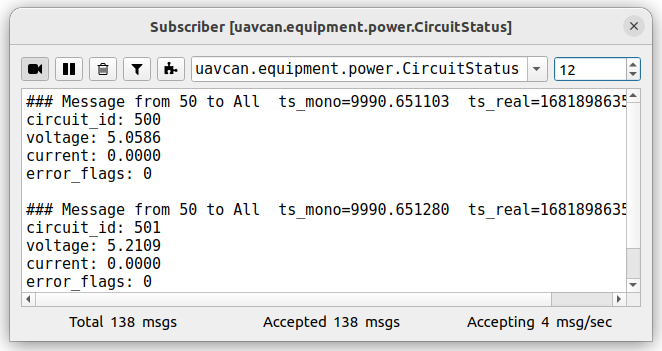
This node as well as any other our nodes measures and sends 5V and Vin voltages as 2 uavcan.equipment.power.CircuitStatus (opens new window) messages
The first message has circuit_id=NODE_ID*10 + 0 and following 3 significant fields:
- voltage - is the 5V voltage
- current - is the max current for the last 0.5 seconds (supported only by
5Anode) - error_flags - might have ERROR_FLAG_OVERVOLTAGE or ERROR_FLAG_UNDERVOLTAGE or non of them
The second message has circuit_id=NODE_ID*10 + 1 and following 3 significant fields:
- voltage - is the Vin voltage
- current - is the average current for the last 0.5 seconds (supported only by
5Anode) - error_flags - ERROR_FLAG_UNDERVOLTAGE or non of them. There is no ERROR_FLAG_OVERVOLTAGE flag because the expected max Vin voltage is unknown.
# 6.2. DroneCAN parameters
The device parameters are devided into a few groups: uavcan, stats, gnss, mag, baro and system.
The list of parameters is shown in the table below:
| Idx | Name | Note | Description |
|---|---|---|---|
| 0 | uavcan.node_id | Reboot required | Node identifier |
| 1 | flight_time_sec | The total flight time in seconds. Doesn't work yet, reserved for future. | |
| 2 | gnss.enable | 0 means disable, 1 means enable gps | |
| 3 | gnss.type | Reboot required | 0 means ublox, 1 means nmea (not supported yet), 2 means ublox emulation (debug only) |
| 4 | gnss.cov_size | immutable | The size of the covariance matrix. Only diagonal matrix of size 6 is supported. Can be extended on request. |
| 5 | gnss.pub_period_ms | 0 means publish which receiving rate, 1-2000 means fixed rate in milliseconds | |
| 6 | gnss.config_delay_ms | 250 ms between sending each command | |
| 7 | gnss.config_request | Reboot required | Force the GNSS configuration if the parameter value is 1 during the initialization of the node. This paramter will automatically set to 0 after the configuration. |
| 8 | gnss.stats_rx | Read only | The total number of RX bytes for the last 10 seconds |
| 9 | gnss.stats_navpvt_rx | Read only | The total number of NavPVT messages for the last 10 seconds |
| 10 | gnss.stats_navstatus_rx | Read only | The total number of NavStatus messages for the last 10 seconds |
| 11 | gnss.stats_navcov_rx | Read only | The total number of NavCov messages for the last 10 seconds |
| 12 | gnss.status | Read only | Bitmask with error codes |
| 13 | gnss.baudrate | Read only | Currently, 921600 is only supported. |
| 14 | crct.enable_5v_check | Set ERROR status if 5V voltage is out of range 4.5 - 5.5 V | |
| 15 | crct.enable_vin_check | Read only | Set ERROR status if Vin voltage is less than 4.5 V. Not implemented yet. |
| 16 | mag.enable | Reboot required | 0 means disable, 1 means enable magnetometer |
| 17 | mag.type | Reboot required | 0 means RM3100 (is recommended, by defaul), 1 means HMC5883L. |
| 18 | mag.pub_frequency | The maximum publish rate. This value is actually limited be the sensor type (mag_type). RM3100 rate is up to 75 Hz. HMC5883L rate is up to 30 Hz. | |
| 19 | mag.status | Read only | Bitmask with error codes |
| 20 | baro.enable | Reboot required | 0 means disable, 1 means enable barometer |
| 21 | baro.pub_frequency | Publish rate | |
| 22 | baro.status | Read only | Bitmask with error codes |
| 23 | system.log_level | Specify what level of log can be sent. Appeared since v0.5.2 | |
| 24 | system.can_bus_check_level | Every CAN bus error will be treated as a specified level of error. Appeared since v0.9.8 | |
| 25 | uavcan.node.name | Reboot required | Custom name of the node. By default the name is Unknown. |
# 6.3. Getting started (bench test)
Before mounting on a real vehicle, especially when using the node for the first time, it is recommended to test the node and perform configuration on a bench using gui_tool (opens new window). This utility allows to easily use the full functionality of the node.
The following checklist allows you to test most of the features and configure the most important parameters.
Step 1. Connect the node to a sniffer. The node should blink.
The simplest connection scheme just for bench testing and configuration is shown below.
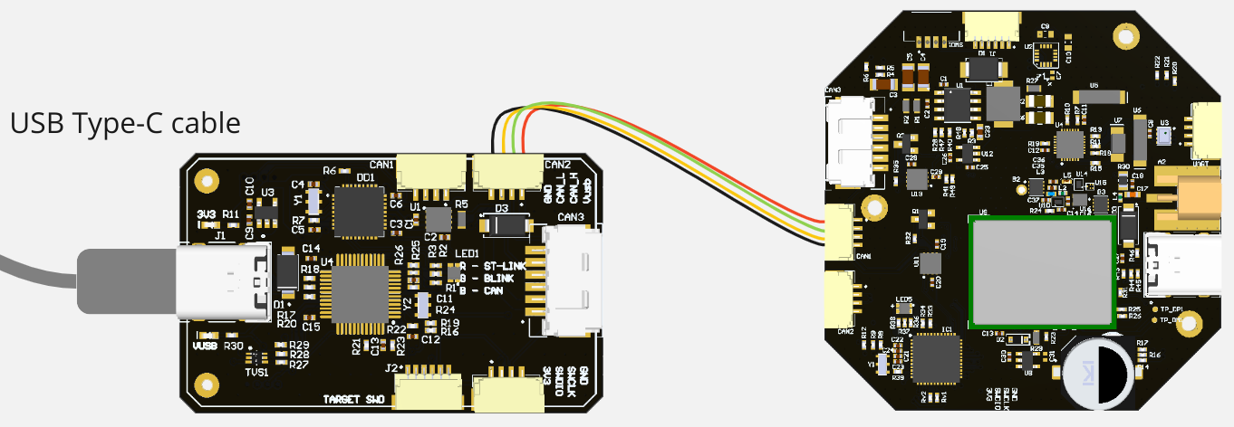
Here, the gnss L1 L2 ZED F9P v3.0 node is connected with a CAN sniffer via JST-GH 4 connector. The sniffer is connected to PC via USB and power the node. The similar connection scheme is valid for any other gnss board.
Alternatively, in a vehicle you may want to connect the node via Molex CAN connector.
By the LED color you can determine the node state:
- Blue/Red blinking means it is in initialization mode. Typically, it takes few seconds.
- Orange blinking means either something is not properly configured or something wrong.
- Red blinking means some critical error. It is related to a software or hardware issue.
- Normally, the node should blink with blue or green color. Green color means that node has 8+ sattelites.
Please, refer to the LED meaning page for details.
Step 2. Open gui_tool and set the local node ID. The node should send data and respond to GetNodeInfo
Apply the Local Node ID by clicking the button in the corresponding field at the top.
Open gui_tool and check that the node publishes some data like NodeStatus and GetNodeInfo. You can quickly press 2 times on the node in Online nodes list. You should be able to see additional information such as node name, software version, UID, etc.
The node should respond with the software version that suits you (probably it should be the latest available stable version).
If your node doesn't send
GetNodeInfoit probably means that your gui_tool is still in anonymous mode. Apply local node ID.
Step 3. Configure the node ID, store parameters, then reboot it. ID value should be updated.
Select the node ID by changing uavcan.node_id that fits your CAN-network without ID-collision.
Step 4. Check CircuitStatus. The node should measure the input voltages and temperature correctly.
Use Tools > Subscriber to look at topics.
If you power a node from USB, the voltage should be ~5V.
The temperature may be a slightly higher than in your room.
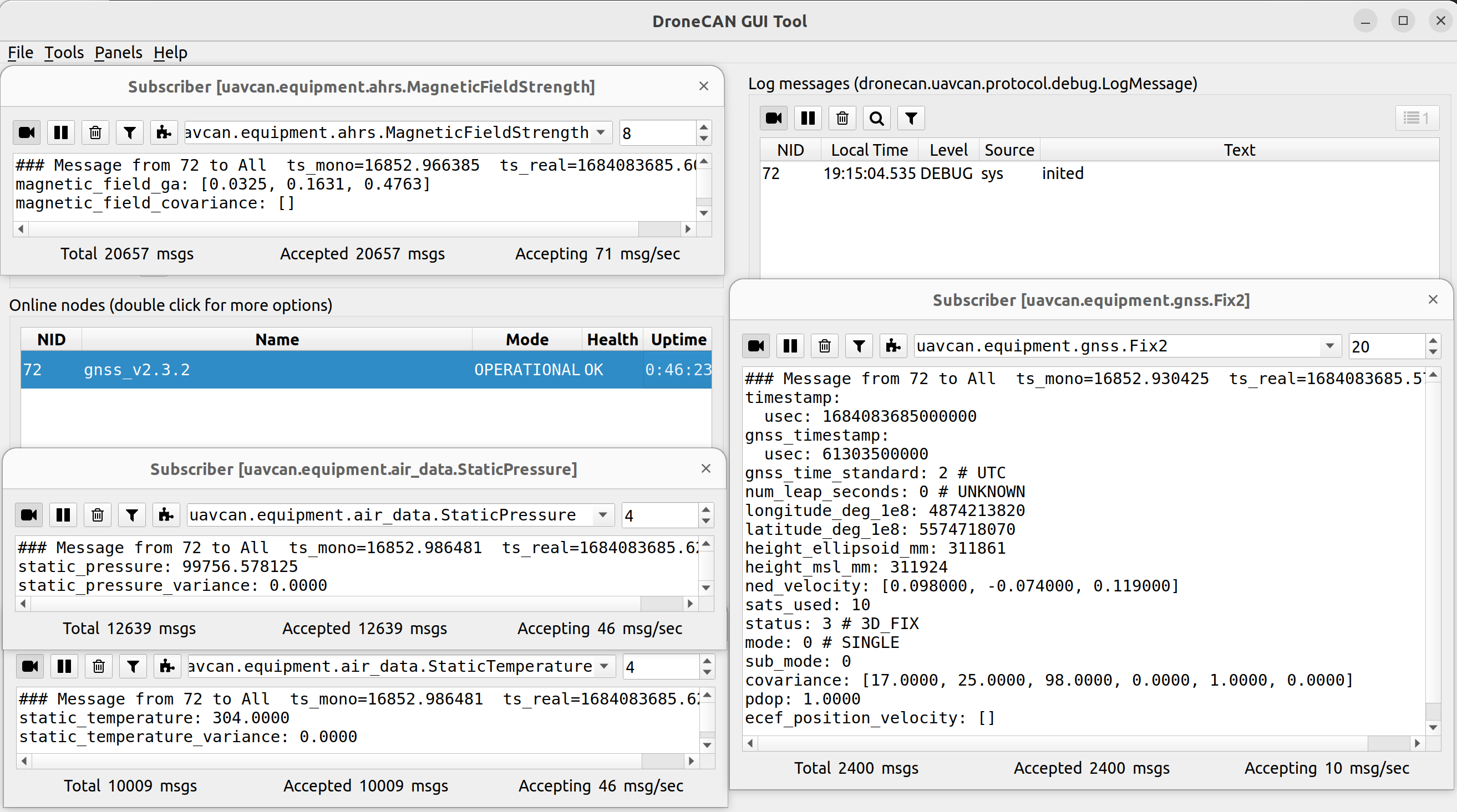
Step 5. Open subscriber panel. The node should publish gnss, magnetometer and barometer data.
Below you can see an example of a messages.
# 6.4. PX4 integration
The node has been tested multiple times on the VTOL application with autopilot based on PX4 with defferent version (v1.12, v1.13, etc).
Typically, you need to setup the following parameters:
- UAVCAN_ENABLE
- UAVCAN_SUB_BARO
- UAVCAN_SUB_GPS
- UAVCAN_SUB_MAG
If the device is configured correctly and the number of used satelites is enough, you will see the vehicle postion in QGC.
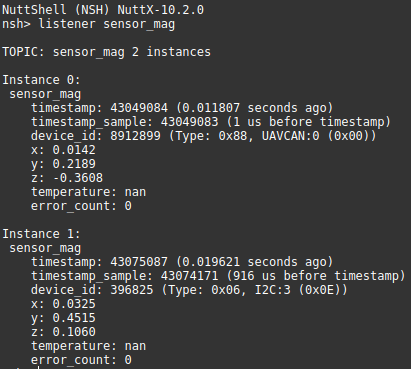
You can visualize the sensor data in MAVLink console. For example, for magnetometer you will see something like on the picture below:
You can also see data in MAVLink Instector for each sensor.
(in process) We have a few particular examples of using this board with PX4 based vehicles:
# 6.5. ArduPilot integration
ArduPilot supports only Fix2 message, so older firmwares are not supoorted.
For DroneCAN GNSS you should set GPS_TYPE = 9.
# 6.6. Software versions
The software is the same for both L1 NEO-M8M and L1/L2 ZED F9P based devices. The only important is to use the proper hardware version.
The following software is related to hardware version v2.3 and higher:
| Version | Description |
|---|---|
| v0.14 ... | Development state. - Add RTK mode, spoofing and jamming bits and more. |
| v0.13.6_7c549af4 (opens new window) Oct 3, 2024 | - Fix ublox UTC timestamp |
| v0.13.5_d9265dd (opens new window) Apr 2, 2024 | - Fix barometer issue |
| v0.12.1_e0ba916 (opens new window) Aug 1, 2023 | - Make warnings less strict - Add gnss baudrate param (read only for a while) |
| v0.11 June, 2023 | - Add automaticall gnss configuration, - Add meaningful default node name (it was unknown by default), - Improve self-diagnostic for gnss and magnetomer, - Add status parameters with error codes, - Add LED idnication for an initialization process. |
| v0.10.19_5e9b7a5 (opens new window) May 17, 2023 | - Fix pdop and covariance (they were integers). |
| v0.10.18_de81a74 (opens new window) May 4, 2023 | - Use Fix2 instead of Fix. - Add covariance, log messages and external LEDs. - Rename all parameters. |
Legacy. The following software is related to hardware version v2.2 and lower:
| Version | Description |
|---|---|
| v0.4.8.2_47ee2ef (opens new window) Apr 5, 2022 | - Several fixes including internal LED, circuit status, barometer temperature, etc |
| v0.4.1.1 6ed1845 (opens new window) Nov 24, 2021 | - Add RGB LEDs |
| v0.2.9_7baa09b (opens new window) Apr 5, 2021 | - Add first release |
For hardware version v3, only Cyphal software is currently supported.