# picoNODE
PicoNode is a general-purpose Cyphal/DroneCAN node based on RP2040 (opens new window). It is capable to generate PWM signals or work with any I2C sensors.
| View | Top view | Bot view |
|---|---|---|
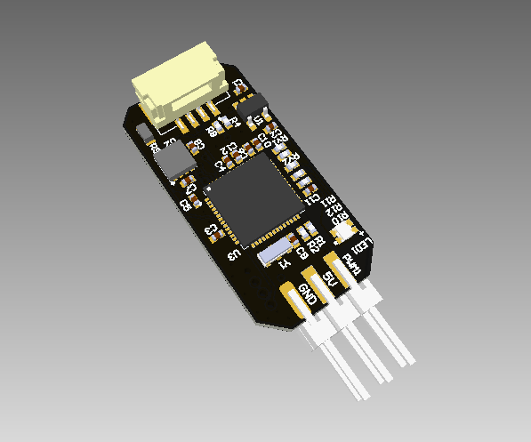 | 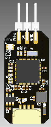 | 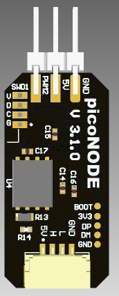 |
# Features
- 2 PWM
- 2 CAN ports
- Voltage sensor
# Wire
Schematic features

Connectors
The node has 3 connectors which are described in the table below.
| № | Connector | Description |
|---|---|---|
| 1 | CAN |
Here you can find manufacturer part number of connectors it self and its mates.
| Type | MP | Suitable Wire Type | MP |
|---|---|---|---|
| CAN1 | JST SM04B-GHS-TB(LF)(SN) | JST 4-pins cable (opens new window) | JST GHR-04V-S (opens new window) and pin SSHL-002T-P0.2 (opens new window) |
Pin configuration and functions
| Pin N | CAN |
|---|---|
| 1 | 5V in |
| 2 | |
| 3 | |
| 4 | GND |
# Specifications
Mechanical
Scheme is shown on the picture below.

| Width, mm | Length, mm | Height, mm | |
|---|---|---|---|
| Outline | |||
| PCB |
Total weight of device less than X g.
Absolute Maximum Ratings
table
Recomended operating conditions
table
ESD ratings
# Description
Functional Block Diagram
Connection example diagram
# Power Supply Recommendations
The uNODE is designed to operate from an input voltage supply range between 4.5 V and 5.5 V. This input supply must be able to withstand the maximum input current and maintain a stable voltage. The resistance of the input supply rail should be low enough that an input current transient does not cause a high enough drop that can cause a false UVLO fault triggering and system reset. The amount of bulk capacitance is not critical, but a 47-μF or 100-μF electrolytic capacitor is a typical choice.
# Revision history
| version | Description |
|---|---|