# DroneCAN Charger node
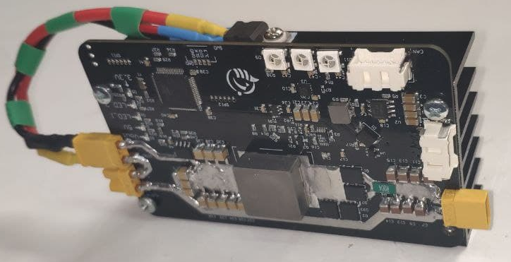
This board allows to automatically charge a battery (up to 4S).

# 1. DroneCAN interface
This node interacts with the following messages:
| № | type | message |
|---|---|---|
| 1 | publisher | inno_msgs.ChargingStatus (opens new window) |
| 2 | publisher | inno_msgs.ChargingControlResponse (opens new window) |
| 3 | publisher | uavcan.equipment.power.CircuitStatus (opens new window) |
| 4 | subscriber | inno_msgs.ChargingControl (opens new window) |
| 5 | subscriber | uavcan.equipment.power.BatteryInfo (opens new window) |
Besides required and highly recommended functions such as NodeStatus and GetNodeInfo this node also supports the following application-level functions:
| № | type | message |
|---|---|---|
| 1 | RPC-service | uavcan.protocol.param (opens new window) |
| 2 | RPC-service | uavcan.protocol.RestartNode (opens new window) |
| 3 | RPC-service | uavcan.protocol.GetTransportStats (opens new window) |
# 2. Hardware specification
(in progress)
# 3. Wire
This board has 4 connectors which may deliver a power to this device. They are described in the table below.
| № | Connector | Description |
|---|---|---|
| 1 | Vin (XT30) | This board consumes more power than a typical UAVCAN node, so it is powered using an additional socket. |
| 2 | UCANPHY Micro (JST-GH 4) | Devices that deliver power to the bus are required to provide 4.9–5.5 V on the bus power line, 5.0 V nominal. Devices that are powered from the bus should expect 4.0–5.5 V on the bus power line. The current shall not exceed 1 A per connector. |
| 3 | 6-pin Molex (502585-0670 (opens new window), 502578-0600 (opens new window)) | Contacts support up to 100 V, 2 A per contact. But the board may work only with 2S-6S. |
| 4 | SWD | STM32 firmware updating using programmer-sniffer. |
It also has following board-specific connectors
| № | Connector | Description |
|---|---|---|
| 5 | V_charging (XT30) | Charging output |
| 5 | DIOD (XT30) |
# 4. Main function description
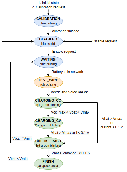
This node might be described using a state machine.
After boot the node is in the CALIBRATION stage - it measures dc-dc output current using ADC multiple times and calculates average raw ADC value - the offset corresponded to the zero current. After the calibration stage, the node goes to the WAITING stage where it is ready for further work. The calibration stage may be repeated only by a specific charing command.
If the node receives start charging command, it goes into the TEST_WIRE stage and then starts charging process.
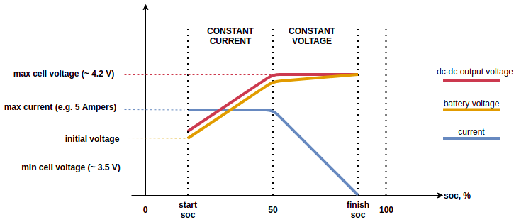
The charging process is divided into 2 main stages. It starts with CHARGING WITH CONSTANT CURRENT (CC) stage then goes into CHARGING WITH CONSTANT VOLTAGE (CV).
If battery voltage is more than maximum voltage (battery is charged) or less than some specific voltage (battery is not connected) or data receiving stops in goes into CHECK FINISH stage. After some checks, it goes into FINISH or WAITING stages or even goes into the previous stage.
The whole state machine might be illustrated using the following flowchart diagram:

The typical 2-stages charging process might be illustrated using the following plot:

During both stages, this node uses I-regulator to keep constant current/voltage.
# 5. Auxiliary functions description
# 5.1. Circuit status
This node as well as any other our nodes measure 5V and Vin voltages and send them in 2 uavcan.equipment.power.CircuitStatus (opens new window) messages.
These voltages might be visualized using our custom custom uavcan_gui_tool (opens new window).
The first message has circuit_id=NODE_ID*10 + 0 and following 3 significant fields:
- voltage - is the 5V voltage
- error_flags - might have ERROR_FLAG_OVERVOLTAGE or ERROR_FLAG_UNDERVOLTAGE or non of them
The second message has circuit_id=NODE_ID*10 + 1 and following 3 significant fields:
- voltage - is the Vin voltage
- error_flags - ERROR_FLAG_UNDERVOLTAGE or non of them. There is no ERROR_FLAG_OVERVOLTAGE flag because the expected max Vin voltage is unknown.
# 5.2. Node info
Every firmware store following info that might be received as a response on NodeInfo request. It stores:
- software version,
- an unique identifier.

# 5.3. Log messages
(in process)
# 6. Parameters
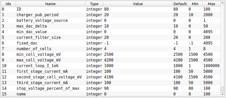
The table with parameters is shown below.

A description of all parameters shown in the tables below.
# 6.1. Common parameters
| № | Parameter name | Reboot required | Description |
|---|---|---|---|
| 0 | ID | true | Node ID |
| 1 | log_level | true | Specify what level of log can be sent. |
| 16 | name | true | Reserved. |
# 6.2. Regulator
| № | Parameter name | Reboot required | Description |
|---|---|---|---|
| 4 | max_dac_delta | true | Limit the maximum change of DAC value per millisecond. |
| 5 | min_dac_value | true | Limit the minimum possible command value. of DAC. |
| 6 | current_filter_size | true | Size of moving average current filter. |
| 11 | current_loop_I_1e6 | true | Integral coefficient. |
| 12 | first_stage_current_mA | true | Desired current on the first stage. |
| 13 | second_stage_cell_voltage_mV | true | Desired voltage on the second stage. |
| 14 | third_stage_current_mA | true | Reserved. |
# 6.3. Battery settings
| № | Parameter name | Reboot required | Description |
|---|---|---|---|
| 8 | number_of_cells | true | Number of battery cells. |
| 9 | min_cell_voltage_mV | true | Min cell voltage of the battery in mV. Measured battery voltage lower than this value will be interpreted as critical. |
| 10 | max_cell_voltage_mV | true | Max cell voltage of the battery in mV. Measured battery voltage higher than this value will indicate that battery is already charged. |
# 6.4. Other
| № | Parameter name | Reboot required | Description |
|---|---|---|---|
| 2 | charger_pub_period | true | Publish rate in milliseconds. |
| 3 | battery_voltage_source | true | 0 means internal voltage source through ADC, 1 means BatteryStatus. |
| 7 | fixed_dac | false | Debug only. 0 means normal usage, other value means specific fixed DAC output. |
| 15 | stop_voltage_percent_of_max | true | When battery charge level reaches this level, the charging will be stopped. |
# 7. Led indication
The board has 3 rgb LEDs which indicate current state of the node.
| № | Stage | Mode | Rgb led |
|---|---|---|---|
| 1 | Calibration | Initialization | Blue pulsing |
| 2 | Disabled | Operational | Blue solid |
| 3 | Waiting | Operational | Blue pulsing |
| 4 | Test wire | Operational | Rgb pulsing |
| 5 | Charging CC | Operational | 1st green blinking, others disabled |
| 6 | Charging CV | Operational | 1st green solid, 2nd green blinking, 3rd disabled |
| 7 | Check finish | Operational | 1st and 2nd green solid, 3rd green blinking |
| 8 | Finish | Operational | All solid |
# 8. Usage example on a table
(in progress)
# 9. Real application usage example
(in progress)