# CAN power connector
CAN power connector are designed for light unmanned aerial (UAV) and other vehicles for providing power over CAN using CAN POWER CABLES.
There are two types of devices:
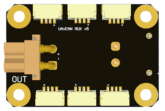
CAN-MUXdevices provide power from XT30 connector to CAN. We have 2 variation of this type of the device with different number of connectors.Power connector nodeis designed to pass current (up to 60A) to power load and CAN, measure voltage and current on load. It behaves as Cyphal/DroneCAN node.
# 1. Variations
At that moment we have 3 types of such connectors. They are illustrated below.
| CAN-MUX v5 | CAN-MUX mini |
|---|---|
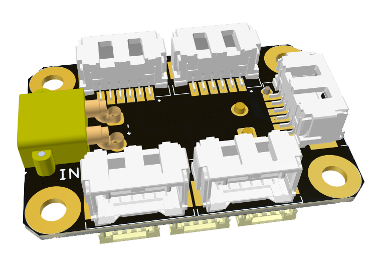 | 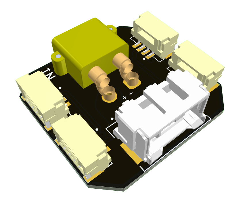 |
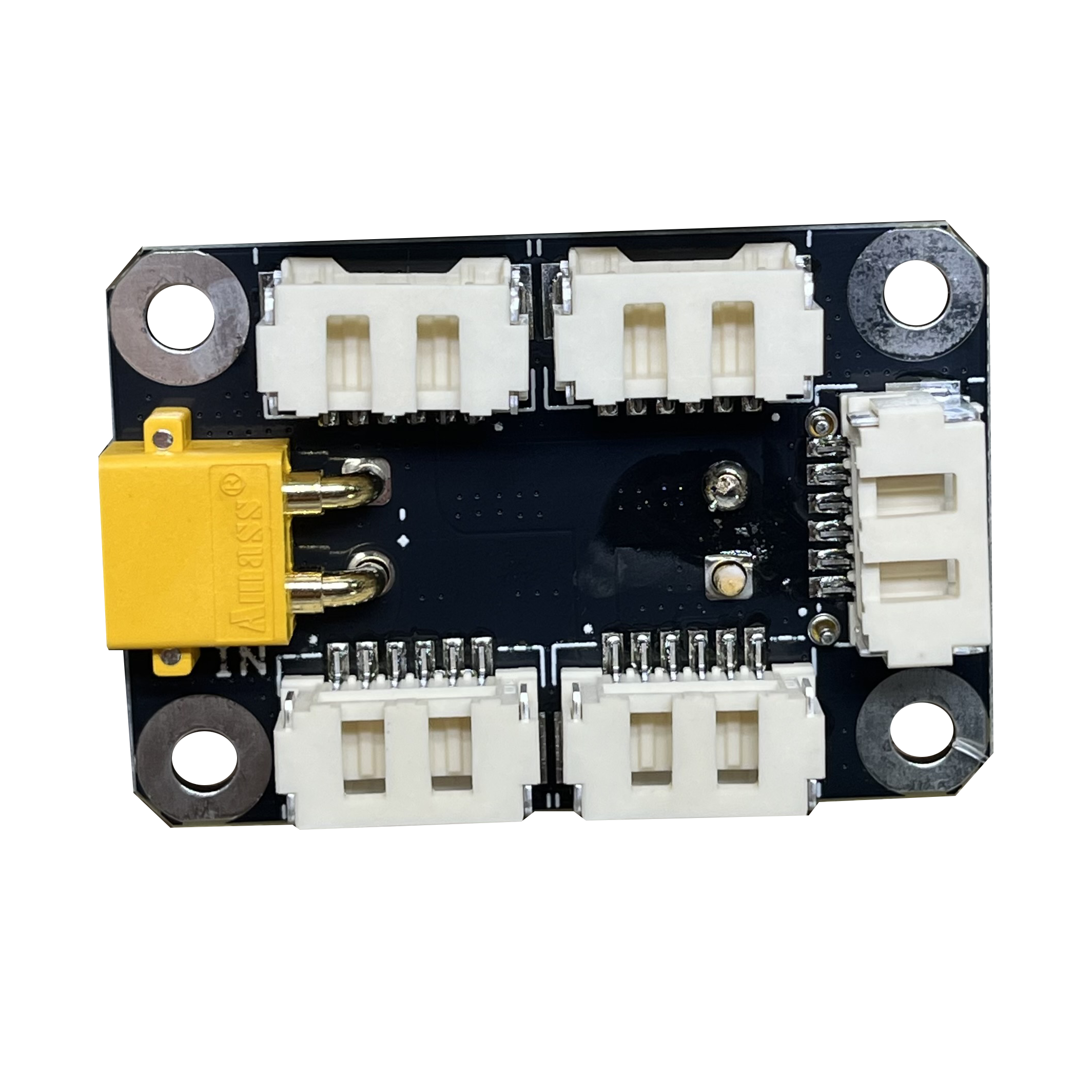
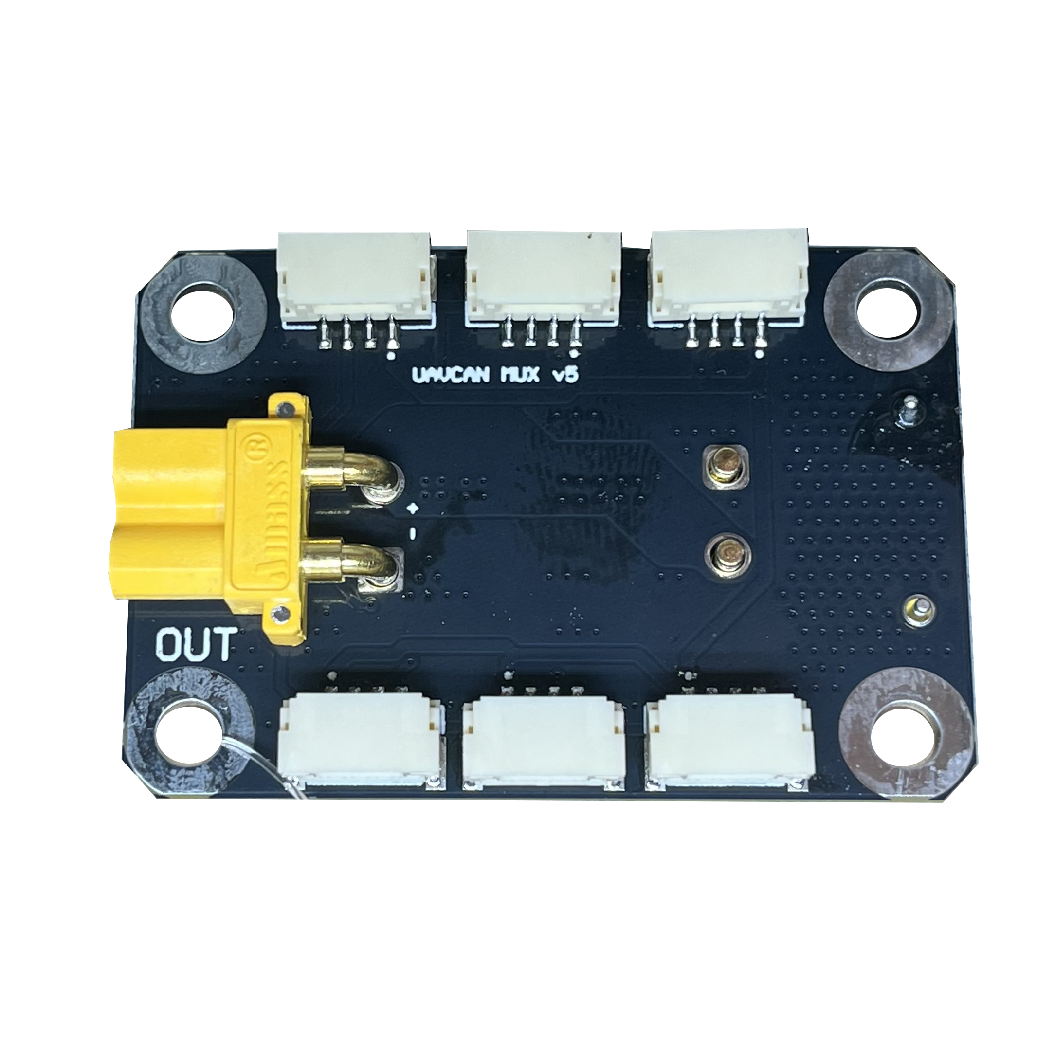
# CAN-MUX v5
| View | Top | Bottom |
|---|---|---|
| 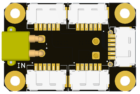 |  |
 |  |
# Connectors
Here you see a schematic showing that XT30 connectors are connected directly to MOLEX (opens new window) 6-pin connectors via power pins and small JST (opens new window) connectors are separated from the high power rail. The CAN HIGH/LOW pins are connected together for MOLEX and JST connectors.

Circuit connections are displayed as a table.
| Connector | V pin | CAN | GND | Comment |
|---|---|---|---|---|
| CAN-Bx | Vin | Yes | Common | Molex 502585-0670 |
| CANx | 5V | Yes | Common | SM04B-GHS-TB(LF)(SN) |
| XT30-x | Vin | No | Common | Power only |
TIP
This device does not provide 5V converted from Vin. This device is only a connector.
# Pin configuration and functions
This table shows the pin assignment for all connectors on the unit.
| Pin N | CANx | Pin N | CAN-Bx | Pin N | XT30-x | ||
|---|---|---|---|---|---|---|---|
| 1 | 5V | 1 | Vin | + | Vin | ||
| 2 | CAN_H | 2 | Vin | - | GND | ||
| 3 | CAN_L | 3 | CAN_H | ||||
| 4 | GND | 4 | CAN_L | ||||
| 5 | GND | ||||||
| 6 | GND |
# Mechanical
Scheme is shown on the picture below. 3d model can be downloaded on GrabCAD (opens new window) (opens new window).

| Width, mm | Length, mm | Height, mm | |
|---|---|---|---|
| Outline | 30.7 | 45.4 | 12.4 |
| PCB | 30.7 | 45.4 | 1.6 |
Total weight of device less than xx g.
# Absolute Maximum Ratings
| Parameter | MIN | MAX | UNIT |
|---|---|---|---|
| Vin (HV) | 5.5 | 55 | V |
| V (LV) | 4.5 | 5.5 | V |
| I max (HV) | 4.0 | A | |
| I max (LV) | 1.0 | A | |
| Operating temperature | -25 | +85 | C |
# Integration
Recommended mechanical mounting
There are no specific recommendations.
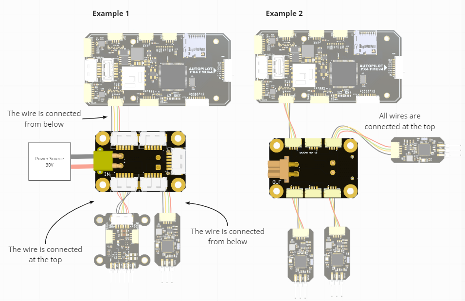
Connection example diagram
Here are the examples:
- The first shows how to use both external high voltage power and 5V CAN power for different nodes with MUX. The NODE (the large one in the left diagram) is connected to a high-voltage power source (here 30 V). In this case, the uNODE (smaller one on the left schematic) is powered directly from the autopilot.
- The second example shows how to connect multiple uNODEs that are powered by the autopilot (5V). If these nodes are powered from a separate DCDC, it (a separate DCDC) should also be connected to one of these connectors.
# CAN-MUX mini 2
The connector without current sensor schematic is shown below.

← 1. Wires 3. Splitter →