# PMU 12S node
# VTOL PMU v2.1.1 hardware
| View | Top | Bottom |
|---|---|---|
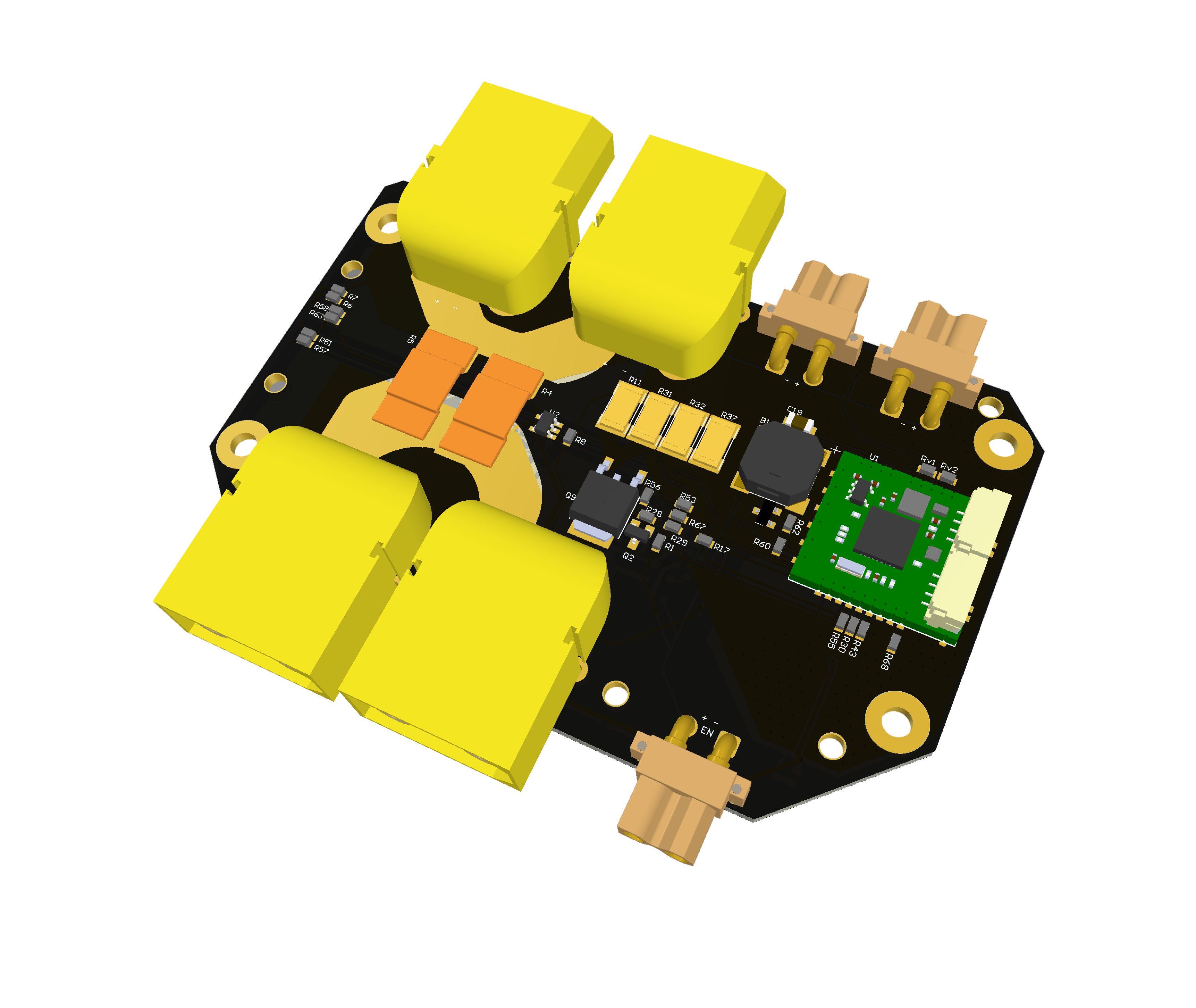 | 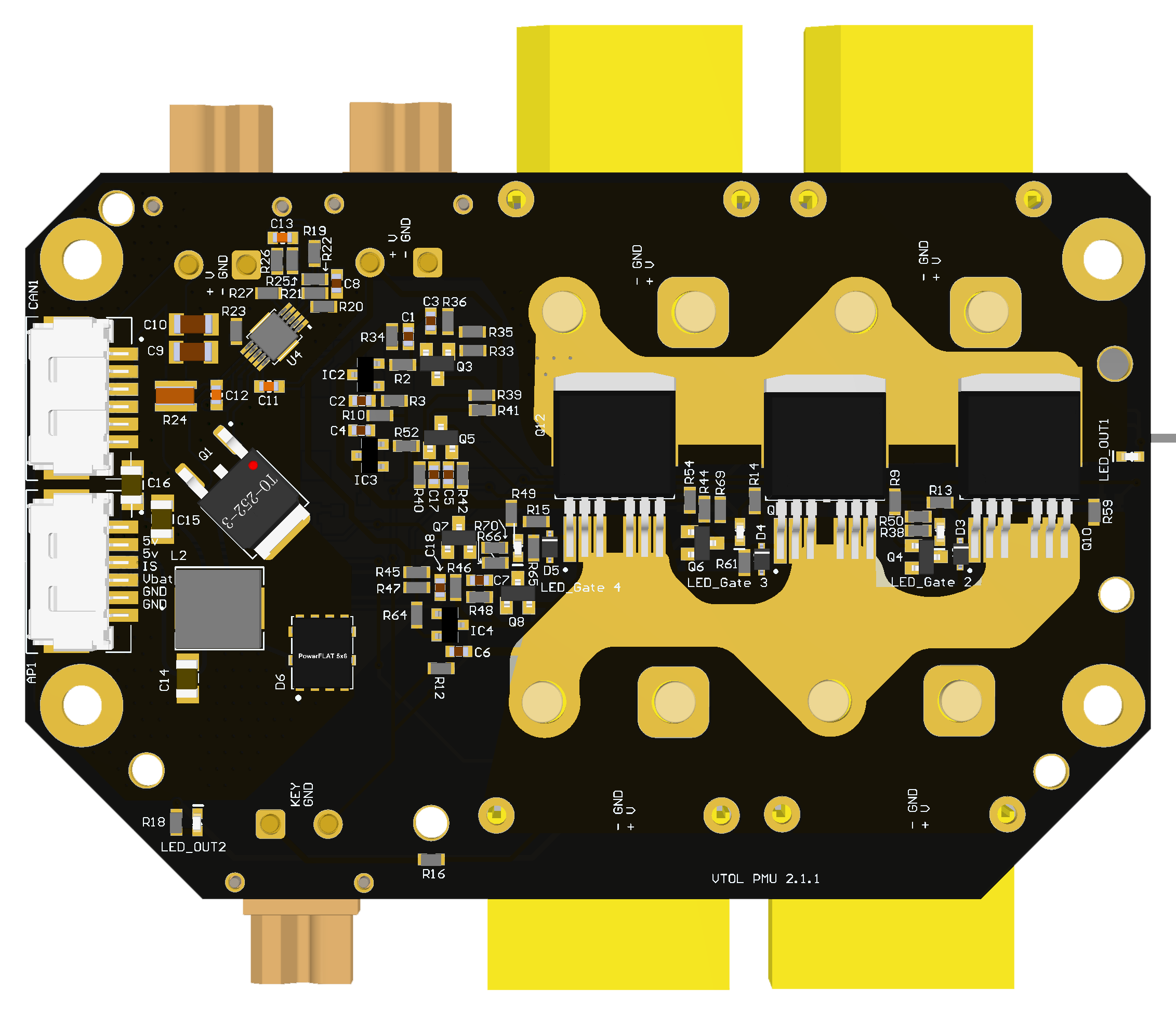 | 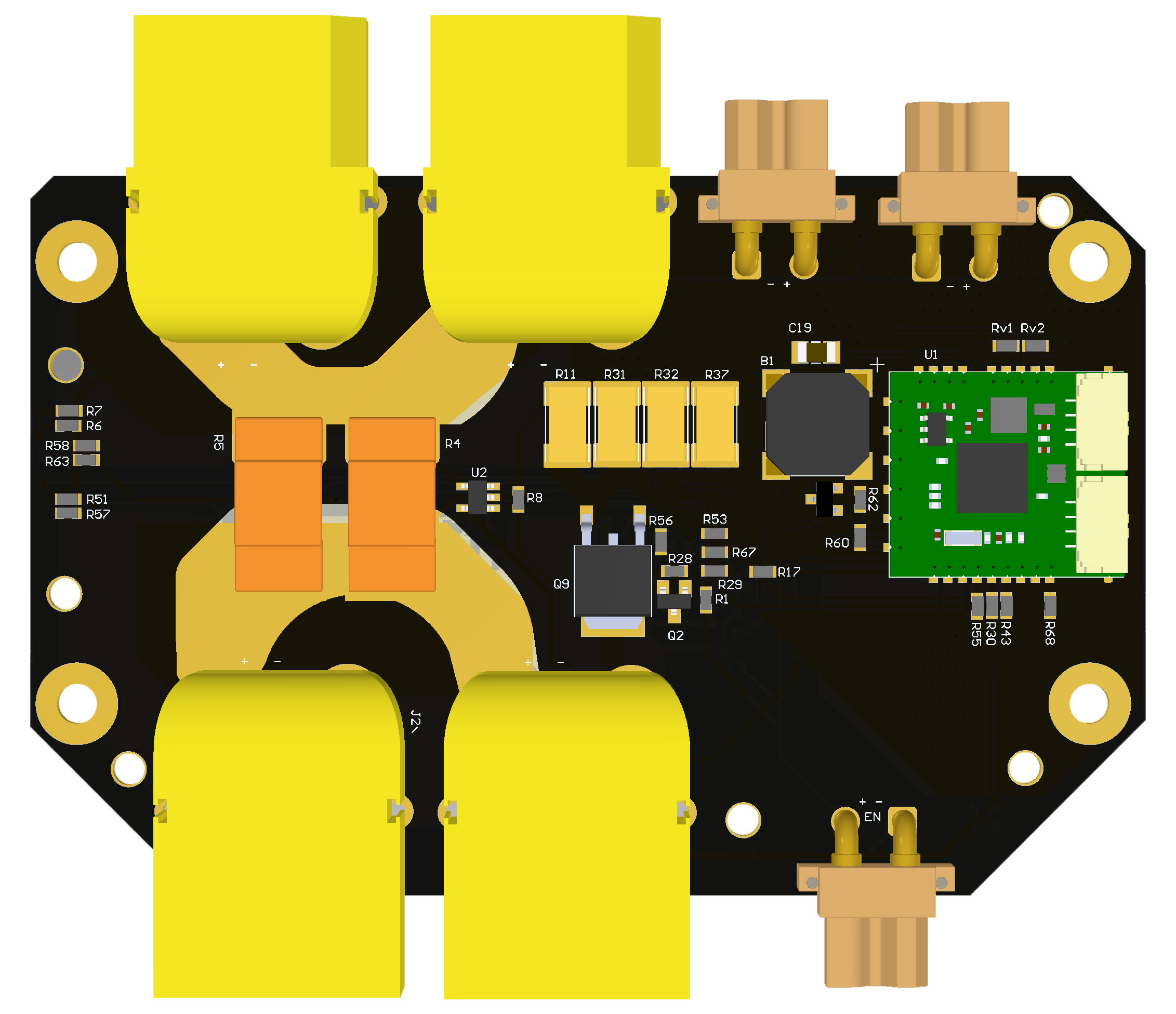 |
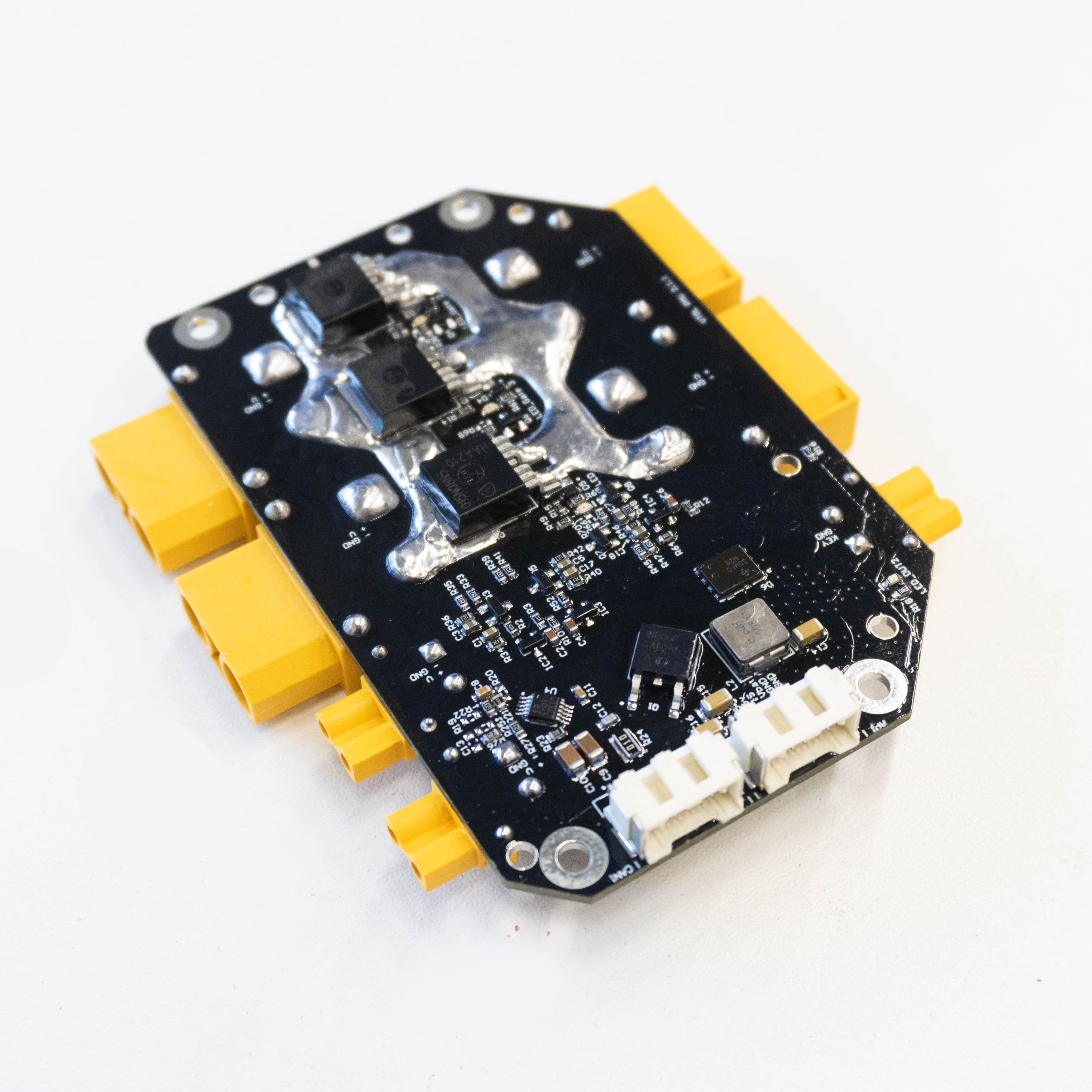 | 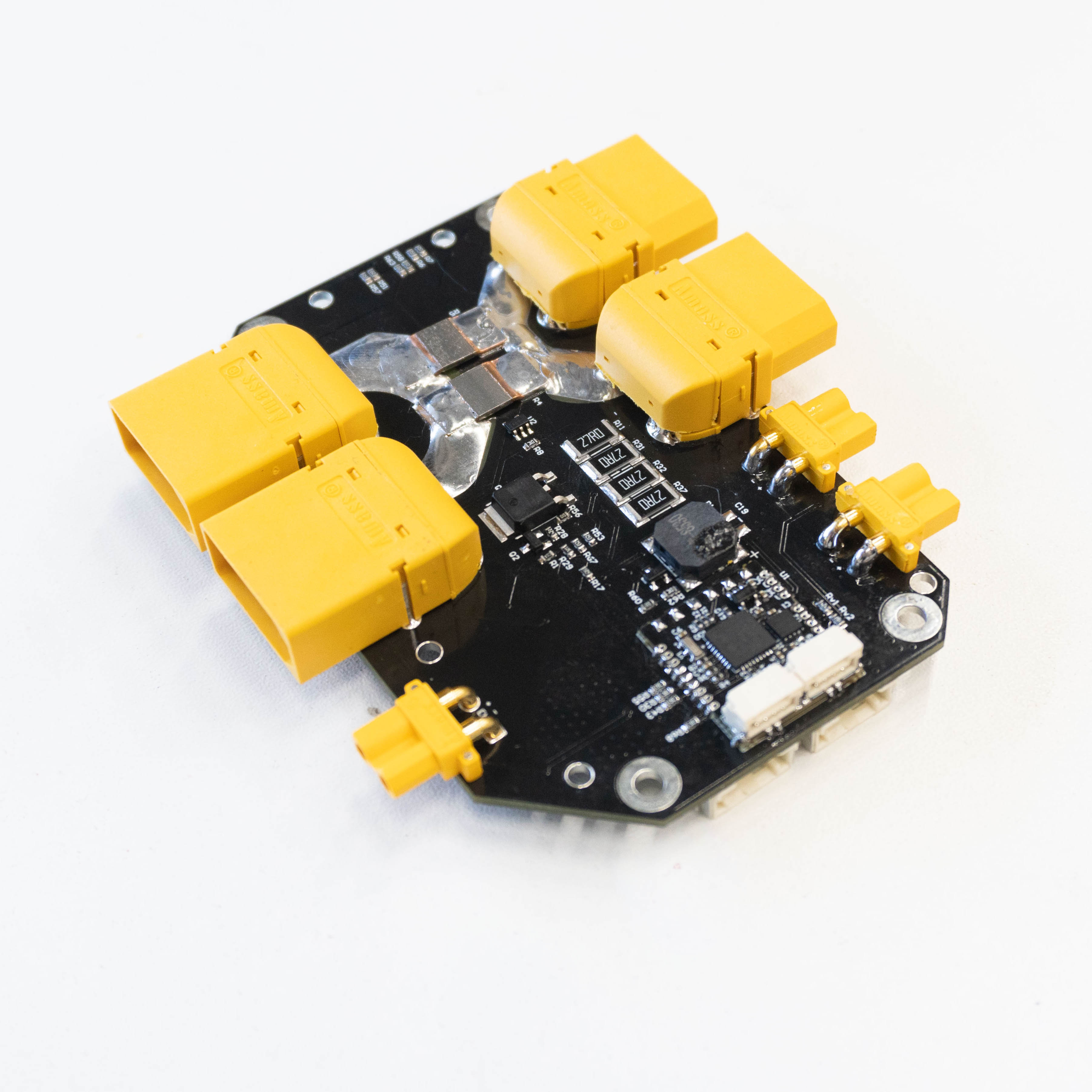 |
# Features
# Wiring
Schematic features. Schematic can be provided via issue.
Connectors
The node has connectors which are described in the table below.
| N | Connector | Description |
|---|---|---|
| 1 | AP1, CAN1 |
Here (opens new window) you can find manufacturer part number of connectors it self and its mates.
# Pin configuration and functions
| Pin N | AP1 | Pin N | CAN1 |
|---|---|---|---|
| 1 | 5V | 1 | Vin |
| 2 | 5V | 2 | Vin |
| 3 | IS | 3 | CAN_H |
| 4 | V_BAT_DIV | 4 | CAN_L |
| 5 | GND | 5 | GND |
| 6 | GND | 6 | GND |
| P1 | GND | P1 | GND |
| P2 | GND | P2 | GND |
Here you can see all connections of MCU.
| MCU PIN | PIN Numer | NET Name | Description |
|---|
# Specifications
Mechanical
Scheme is shown on the picture below. CAN model can be provided via email request or issue on github or downloaded on GrabCAD (opens new window) (opens new window).
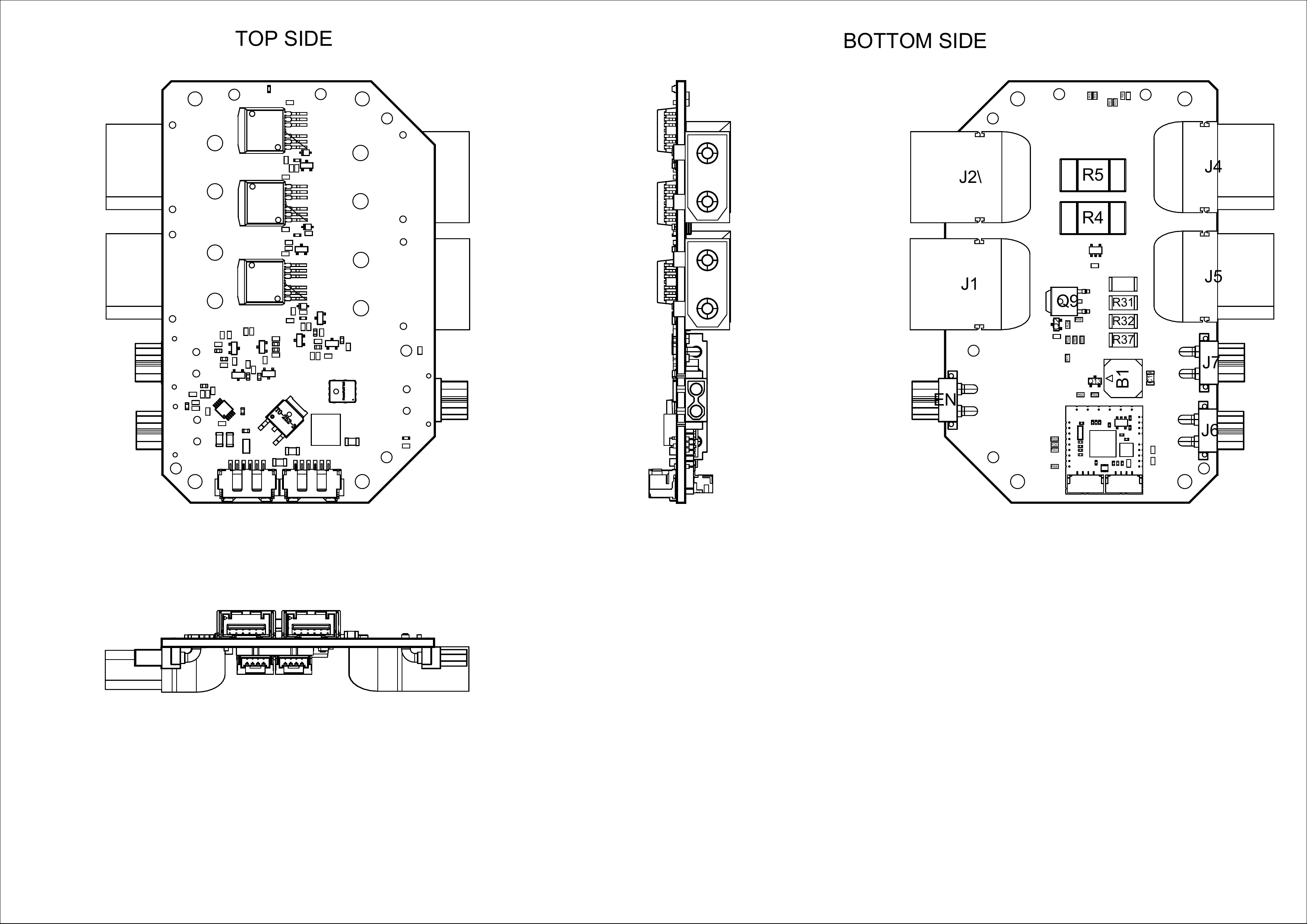
| Width, mm | Length, mm | Height, mm | |
|---|---|---|---|
| Outline | 95.8 | 82.6 | 18.5 |
| PCB | 95.8 | 61.87 | 2.0 |
Total weight of device less than 50 g.
# Housing
Information about case presented here.
# Absolute Maximum Ratings
# Recommended operating conditions
# ESD ratings
# MTFF
# Integration
Recommended mechanical mounting
Connection example diagram
# Power Supply Recommendations
Device is designed to operate from an input voltage supply range between 4.5 V and 5.5 V over CAN2 or CAN3 connector, or 5.5 - 30 V from CAN1. This input supply must be able to withstand the maximum input current and maintain a stable voltage. The resistance of the input supply rail should be low enough that an input current transient does not cause a high enough drop that can cause a false UVLO fault triggering and system reset. The amount of bulk capacitance is not critical, but a 47-uF or 100-uF electrolytic capacitor is a typical choice.
# Revision history
| View | Version | Date | Description |
|---|
# DroneCAN interface
This node interacts with the following messages:
| № | type | message |
|---|---|---|
| 1 | publisher | uavcan.equipment.power.BatteryInfo (opens new window) |
| 2 | publisher | uavcan.equipment.power.CircuitStatus (opens new window) |
| № | type | message |
|---|---|---|
| 1 | RPC-service | uavcan.protocol.param (opens new window) |
| 2 | RPC-service | uavcan.protocol.RestartNode (opens new window) |
| 3 | RPC-service | uavcan.protocol.GetTransportStats (opens new window) |
# Other
There are 4 gates. First one always works and is dedicated for smooth startup. Second, third and fourth are used in flight.
| DMA Rank | Periphery | Pin | Meaning | Note |
|---|---|---|---|---|
| 0 | ADC_IN0 | PA0 | ADC_VIN | k = 19 |
| 1 | ADC_IN2 | PA2 | ADC_GATE_2 | If voltage < 1.4 V, so it is broken. |
| 2 | ADC_IN3 | PA3 | ADC_CURRENT | 0 amper - 0V, 600 amper - 3V |
| 3 | ADC_IN4 | PA4 | ADC_GATE_3 | If voltage < 1.4 V, so it is broken. |
| 4 | ADC_IN6 | PA6 | ADC_GATE_4 | If voltage < 1.4 V, so it is broken. |
| 5 | Temperature | - | stm32 temperature sensor |