# Splitter
The splitter is designed to be used on drones with CAN bus on board. It allows more complex bus topologies than star or ring. There are two versions of the boards.
# Features
- Can be powered from up to 30 V
- Separate two CAN buses
- Prevent of propagation of High and Low line shortage
# Variants
The (Splitter) version decouples the physical layer of the CAN interface. And the version (Splitter-Isolated) besides the physical isolation of the CAN interface is also galvanically isolated.
| Not Isolated | Isolated |
|---|---|
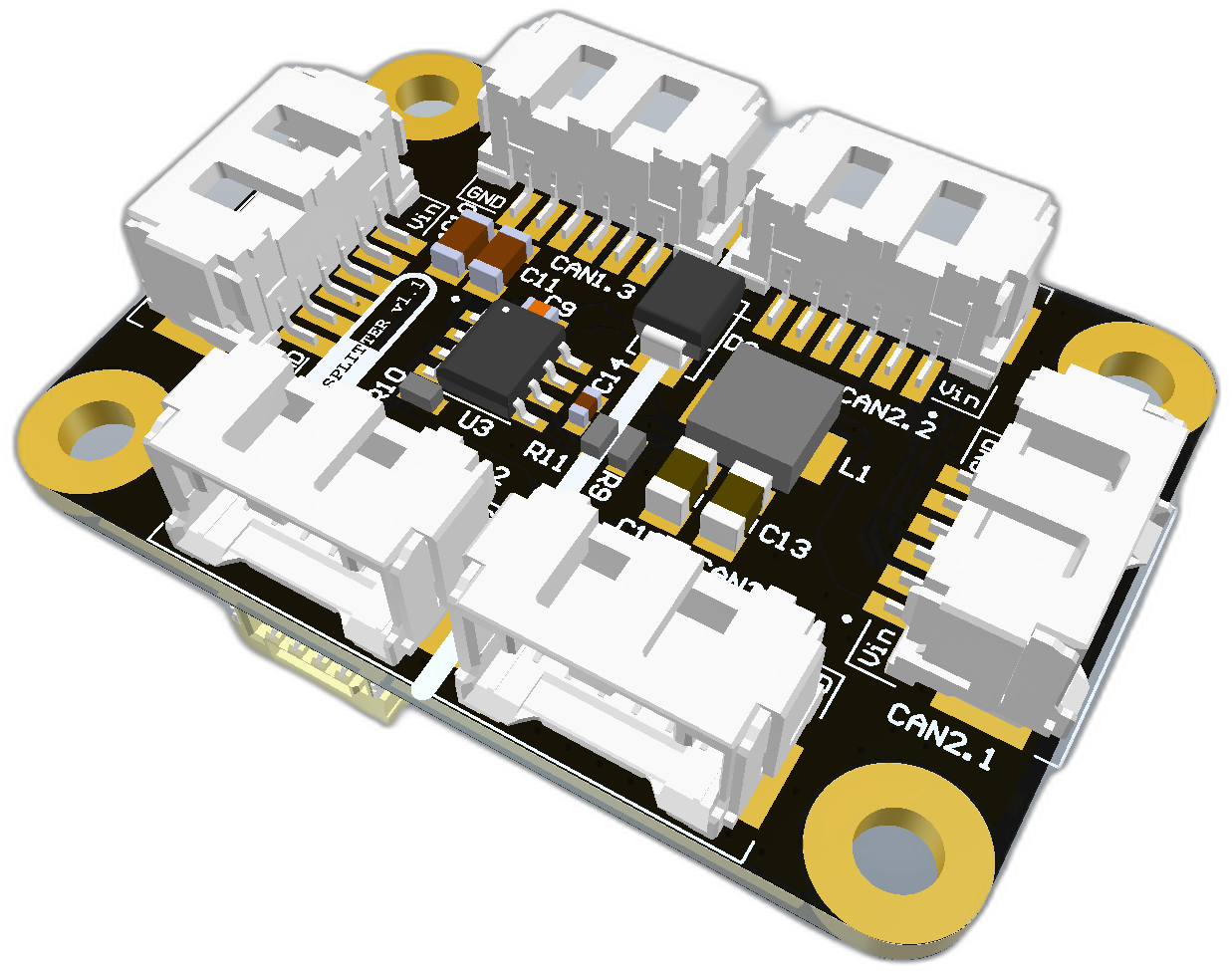 |  |
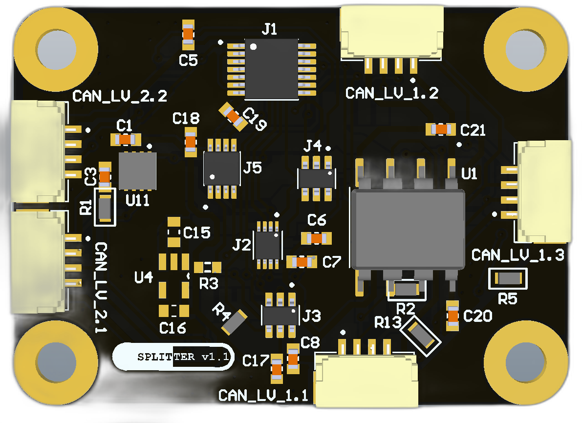
# Splitter v110
| View | Top | Bottom |
|---|---|---|
| 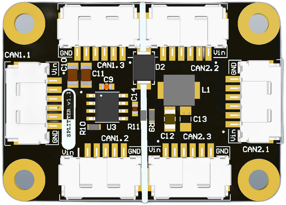 |  |
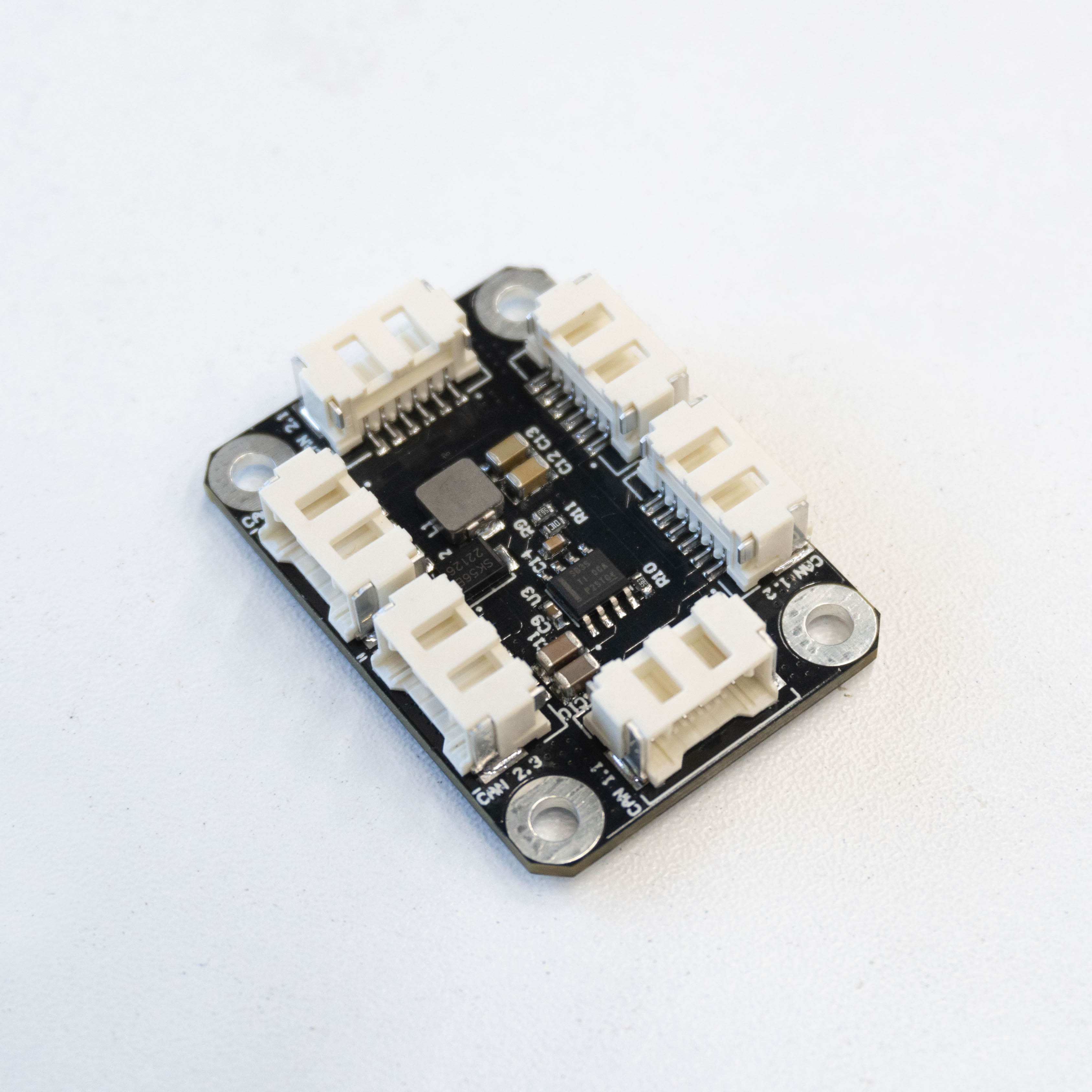 | 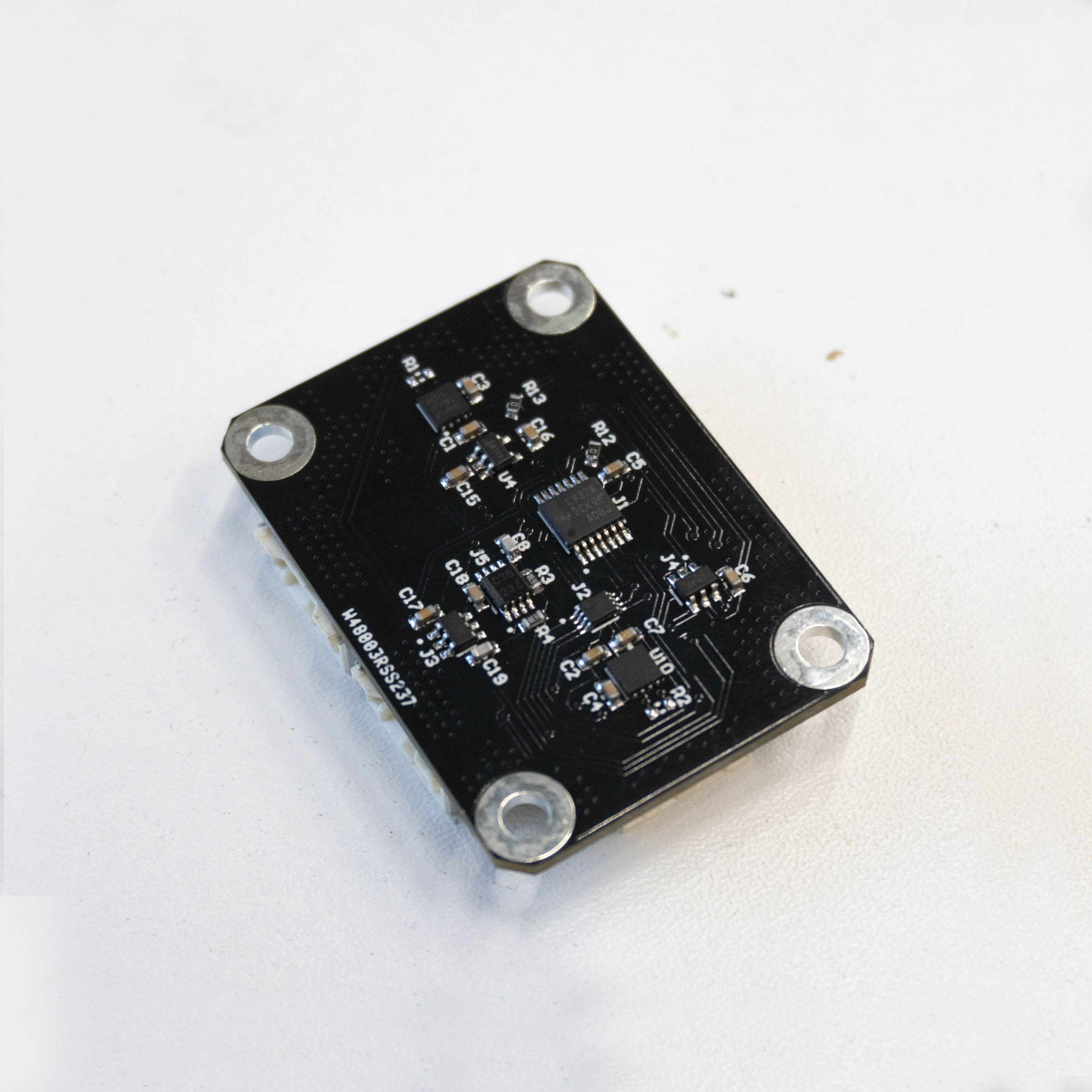 |
Connectors
The node has connectors which are described in the table below.
| N | Connector | Description |
|---|---|---|
| 1 | CAN 1.1 CAN 1.2 CAN 1.3 | This connectors wired together with A side of CAN decoupler, can be powered from high voltage |
| 2 | CAN LV 1.1 CAN LV 1.2 CAN LV 1.3 | A side of CAN decoupler, can be powered from 4.8-5.2V or internal DC-DC if high power is connected. |
| 3 | CAN 2.1 CAN 2.2 CAN 2.3 | Wired together with B side of CAN decoupler, can be powered from high voltage |
| 4 | CAN LV 2.1 CAN LV 2.2 CAN LV 3.3 | B side of CAN decoupler, can be powered from 4.8-5.2V or internal DC-DC if high power is connected. |
Here (opens new window) you can find manufacturer part number of connectors it self and its mates.
# Specifications
Mechanical
Scheme is shown on the picture below. CAN model can be provided via email request or issue on github or downloaded on GrabCAD (opens new window).
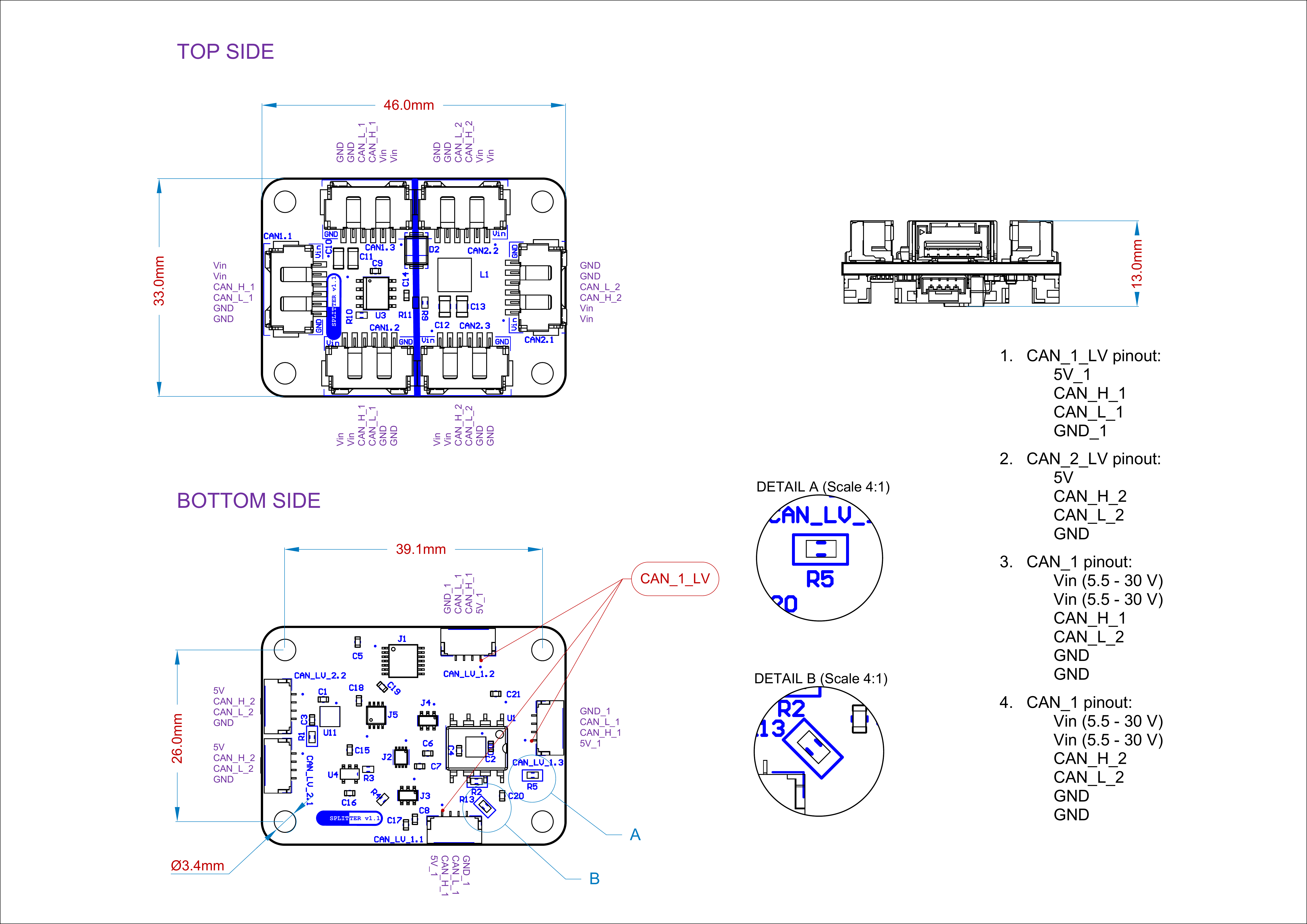
| Width, mm | Length, mm | Height, mm | |
|---|---|---|---|
| Outline | 46.0 | 33.0 | 13.0 |
| PCB | 46.0 | 33.0 | 1.6 |
Total weight of device less than 50 g.
# Housing
Information about case presented here.
# Absolute Maximum Ratings
| Parameter | MIN | MAX | UNIT |
|---|---|---|---|
| V (CAN HV) | -0.3 | 65 | V |
| V (CAN LV) | -0.3 | 7 | V |
| I max | A | ||
| Storage temperature | -65 | +150 | C |
# Recommended operating conditions
| Parameter | MIN | MAX | UNIT |
|---|---|---|---|
| V (CAN HV) | -0.3 | 65 | V |
| V (CAN LV) | 4.5 | 5.5 | V |
| Operating temperature | -25 | +85 | C |
# ESD ratings
| Description | Value | UNIT |
|---|---|---|
| Human-body model (HBM) | 2000 | V |
| Charged-device model (CDM) | 750 | V |
| Machine model | 200 | V |
# MTFF
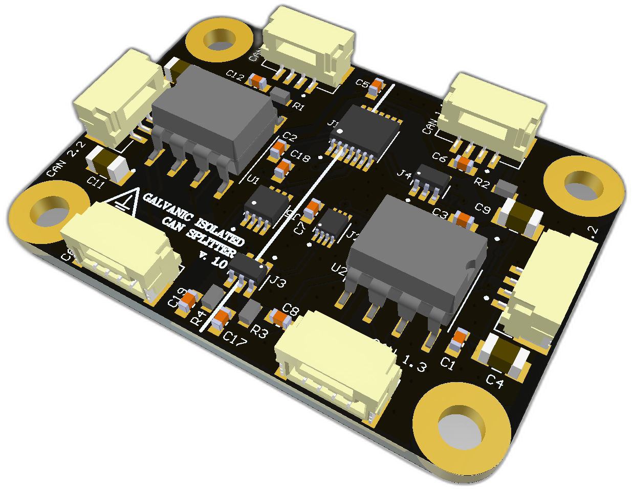
# Splitter Isolated v100
| View | Top | Bottom |
|---|---|---|
| 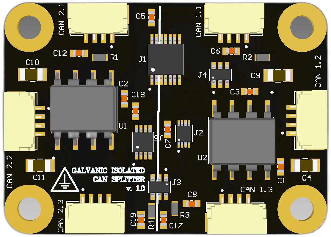 |  |
| |
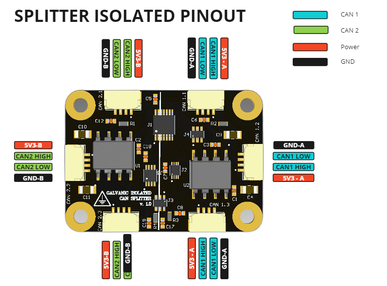
Connectors
The node has connectors which are described in the table below.
| N | Connector | Description |
|---|---|---|
| 1 | CAN LV 1.1 CAN LV 1.2 CAN LV 1.3 | This connectors wired together with A side of CAN decoupler, should be powered from 4.8-5.2V. |
| 2 | CAN LV 2.1 CAN LV 2.2 CAN LV 3.3 | B side of CAN decoupler, should be powered from 4.8-5.2V. |
Here (opens new window) you can find manufacturer part number of connectors it self and its mates.
# Specifications
Mechanical
Scheme is shown on the picture below. CAN model can be provided via email request or issue on github or downloaded on GrabCAD (opens new window).
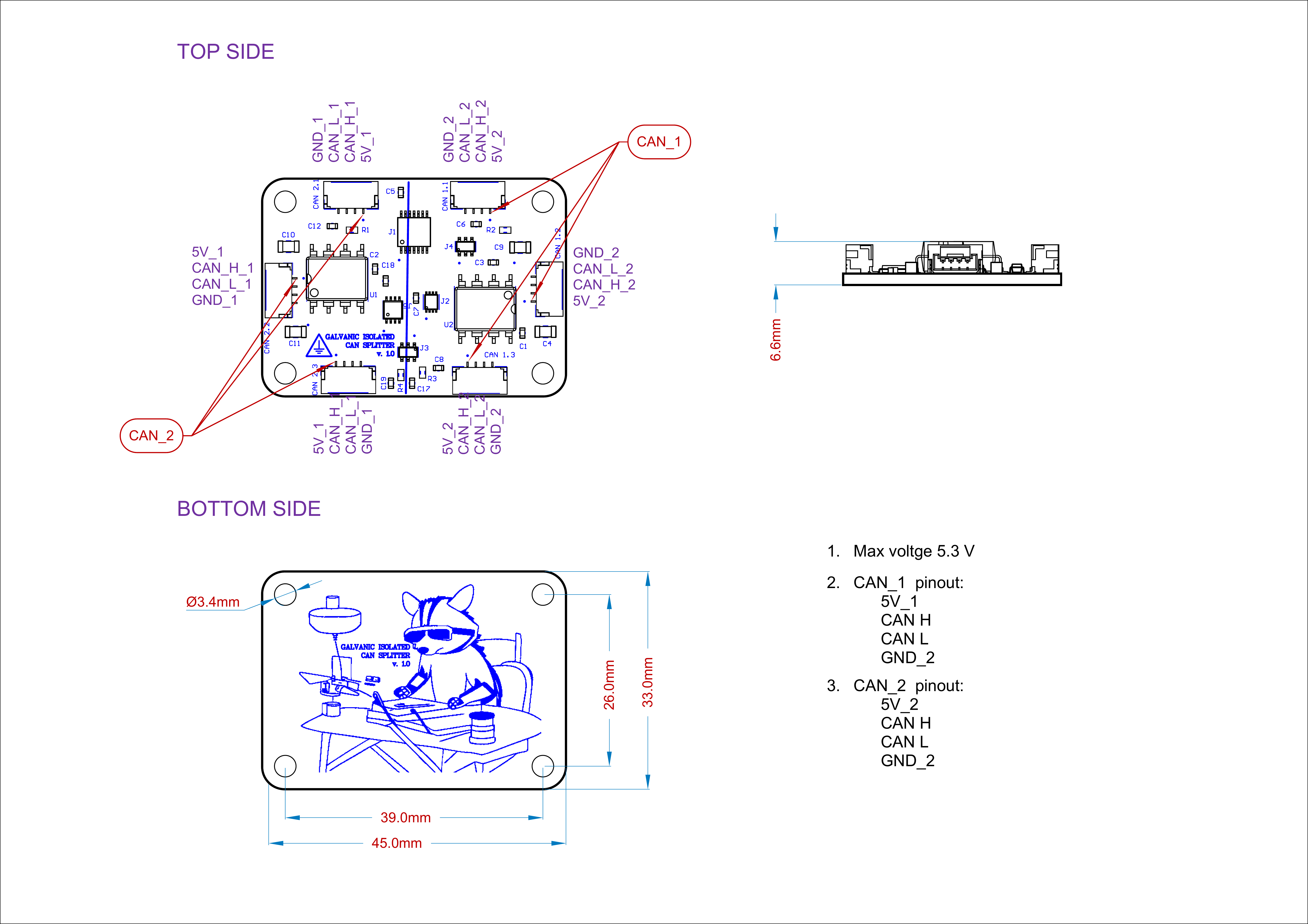
| Width, mm | Length, mm | Height, mm | |
|---|---|---|---|
| Outline | 46.0 | 33.0 | 13.0 |
| PCB | 46.0 | 33.0 | 1.6 |
Total weight of device less than 50 g.
# Housing
Information about case presented here.
# Absolute Maximum Ratings
| Parameter | MIN | MAX | UNIT |
|---|---|---|---|
| V (CAN1.x, CAN2.x) | -0.5 | 6 | V |
| I | A | ||
| Storage temperature | -65 | +150 | C |
# Recommended operating conditions
| Parameter | MIN | MAX | UNIT |
|---|---|---|---|
| V (CAN1.x, CAN2.x) | 3 | 5.5 | V |
| Operating temperature | -25 | +85 | C |
# ESD ratings
| Description | Value | UNIT |
|---|---|---|
| Human-body model (HBM) | 2000 | V |
| Charged-device model (CDM) | 1000 | V |
| Machine model | 200 | V |
# MTFF
# Integration
Recommended mechanical mounting
Mounting type not specified.
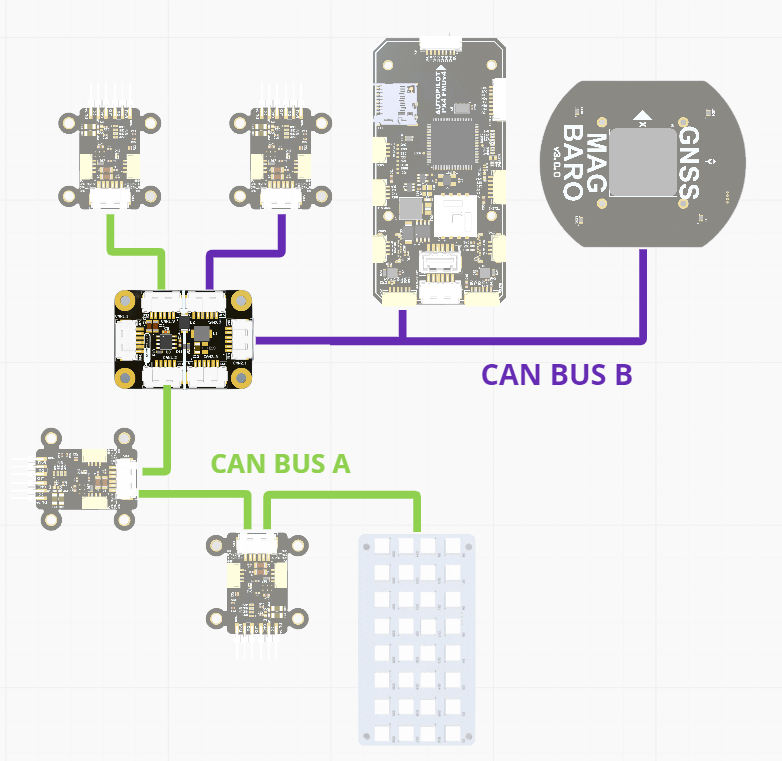
Connection example diagram
Typically, the isolated variant can be connected between two nodes with separate power sources to isolate them. For example, it can be used in the case of a bus loop.
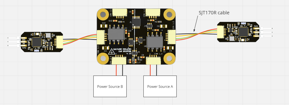
Another use of non-galvanically isolated devices is to create a complex bus network, as in this.
# Power Supply Recommendations
Device is designed to operate from an input voltage supply range between 4.5 V and 5.5 V over CAN LV connector, or 5.5 - 30 V from CAN HV. This input supply must be able to withstand the maximum input current and maintain a stable voltage. The resistance of the input supply rail should be low enough that an input current transient does not cause a high enough drop that can cause a false UVLO fault triggering and system reset. The amount of bulk capacitance is not critical, but a 47-uF or 100-uF electrolytic capacitor is a typical choice.
# Revision history
| View | Version | Date | Description |
|---|---|---|---|
| 0.1.0 | 20 Jan 2023 | proof of concept |