# 2. Hardware
| View | Top view | Bot view |
|---|---|---|
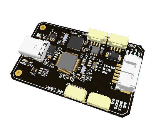 | 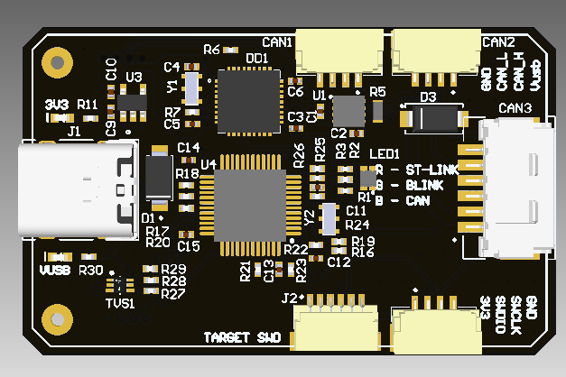 | 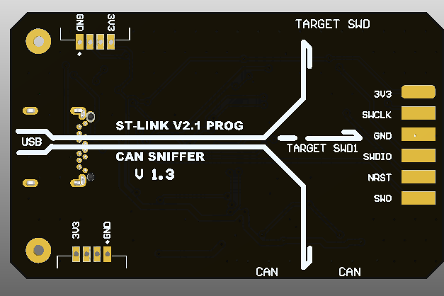 |
 | 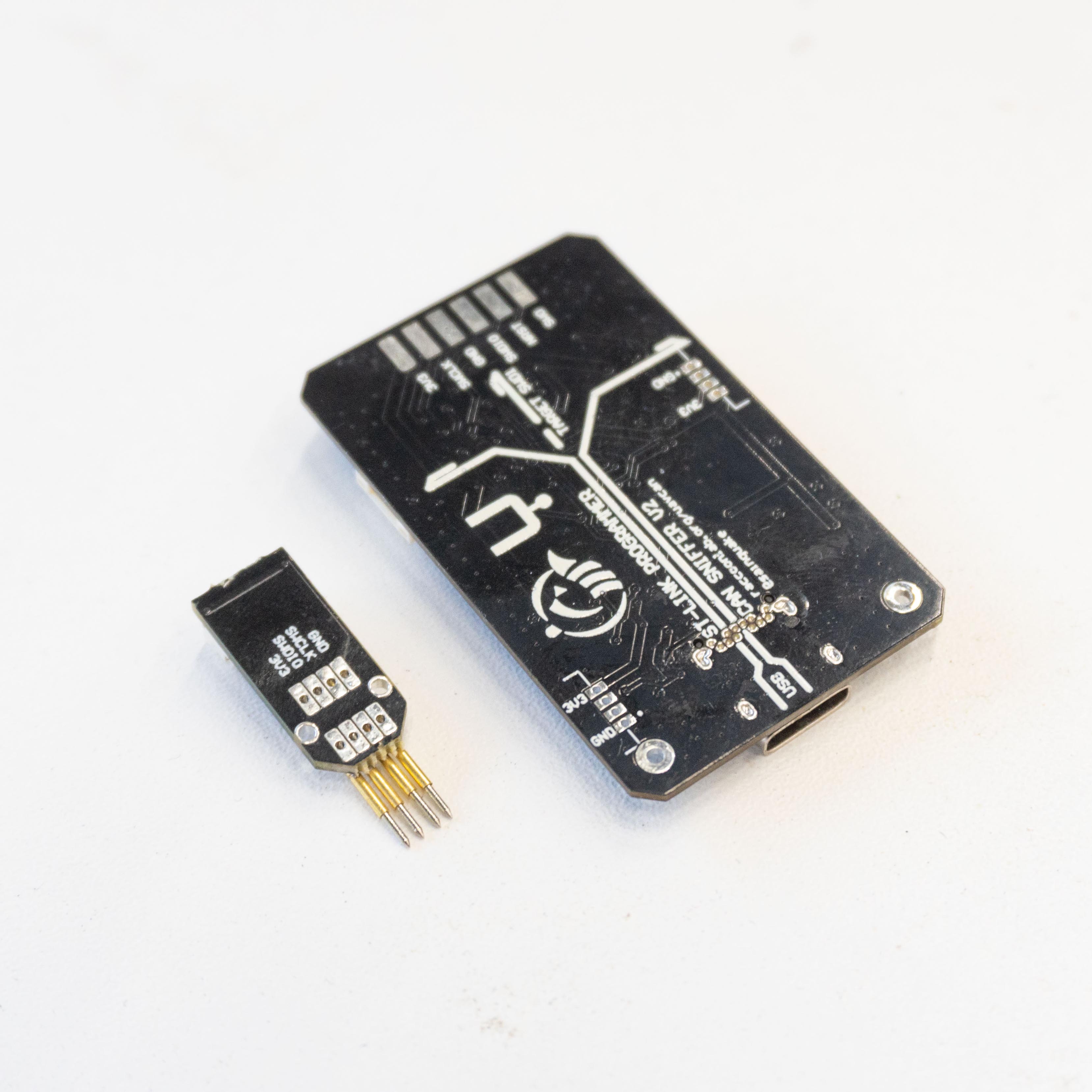 |
# 2.1. Features
- Sniffer and programmer in one board;
- USB-C interface;
- LED indication;
- 2 different CAN sockets including UCANPHY Micro (JST-GH 4) and 6-pin Molex;
- Compact design;
- Cyphal/DroneCAN HITL support;
- LxWxH: 52x32x8 mm
- Weight: 10 g
# 2.2. Wire
Schematic represented in this repo (opens new window), and PDF version is here (opens new window)
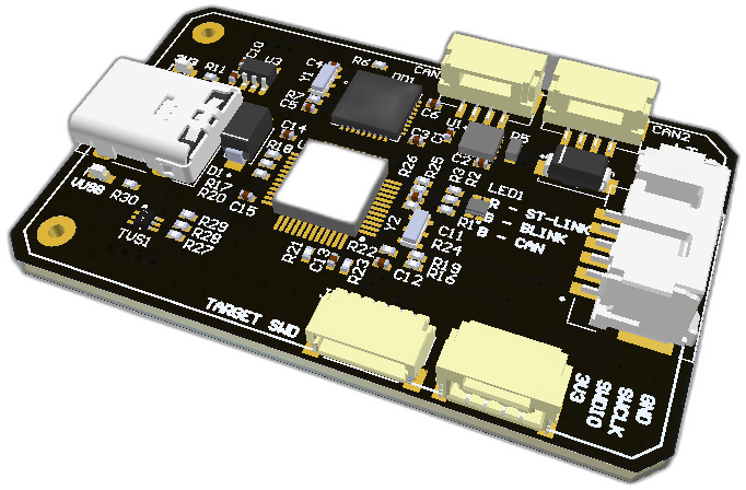
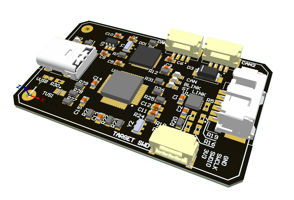
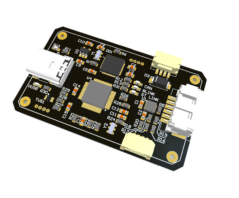
Connectors
The node has 5 connectors which are described in the table below.
| № | Connector | Description |
|---|---|---|
| 1 | USB Type-C | Dedicated for connection with PC |
| 2 | CAN1, CAN2 | Devices that deliver power to the bus are required to provide 4.5–5.5 V on the bus power line, 5.0 V nominal. Devices that are powered from the bus should expect 4.5–5.5 V on the bus power line. The current shall not exceed 1 A per connector |
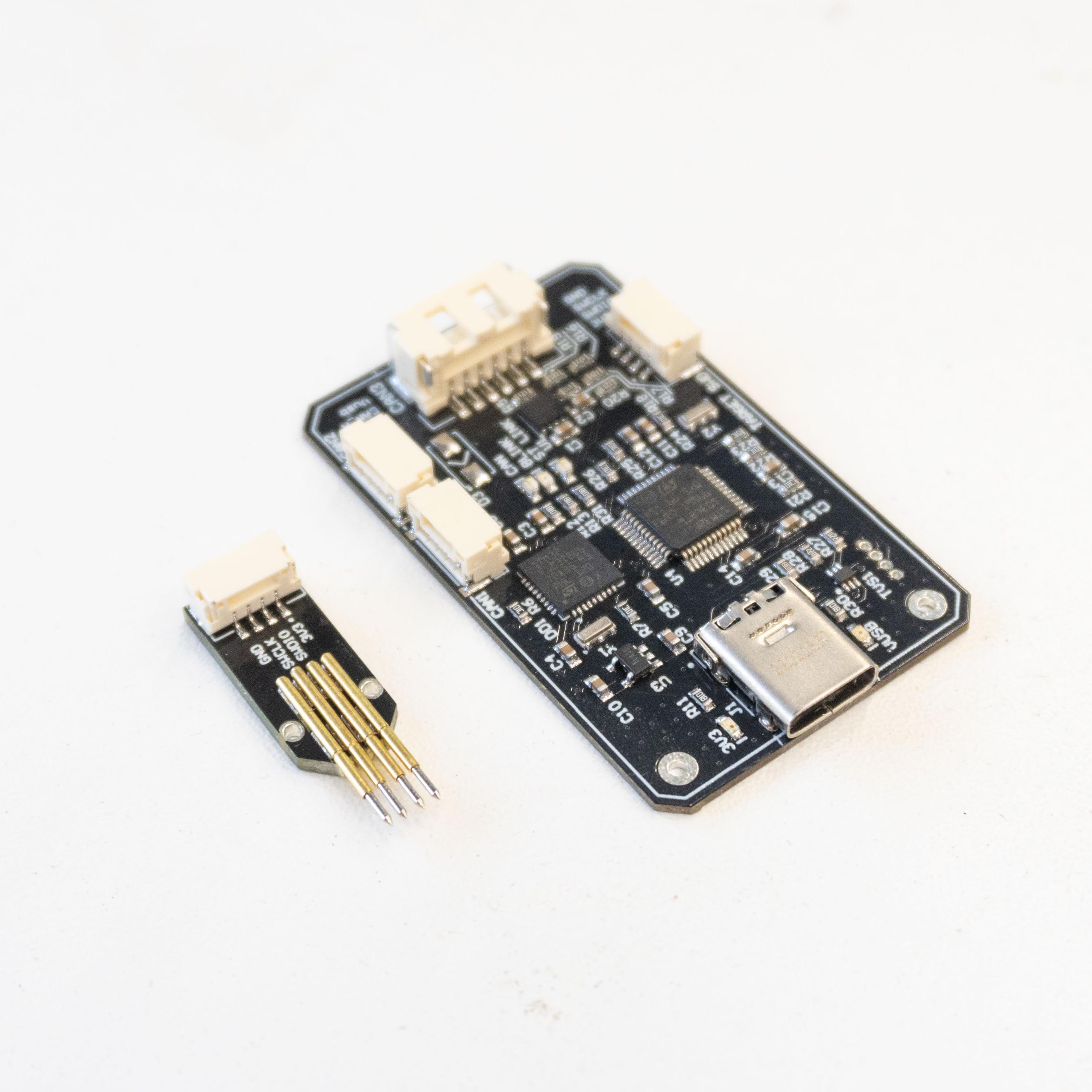
| 3 | SWD | STM32 firmware updating using programmer-sniffer |
| 4 | J1 | Debug connector matches with Zubax probe (opens new window) |
| 5 | CAN3 | Designed to be compatible with standard (opens new window) |
WARNING
Be careful, 4-pin CAN and SWD connectors look similar, but the wrong connection may cause some problems. Names of these connectors are marked on the backside of the board.
Pin configuration and functions
| Pin | CAN3 | CAN1, CAN2 | SWD | DEBUG |
|---|---|---|---|---|
| 1 | Vin | 5V in | GND | 3.3V |
| 2 | Vin | CAN High | SWCLK | NC |
| 3 | CAN High | CAN Low | SWDIO | NC |
| 4 | CAN Low | GND | 3.3V | SWDIO |
| 5 | GND | SWCLK | ||
| 6 | GND | GND |
# 2.3. Specifications
Mechanical
Scheme is shown on the picture below. CAN model can be provided via email request or issue on github or downloaded on GrabCAD (opens new window).

| Width, mm | Length, mm | Height, mm | |
|---|---|---|---|
| Outline | 51.9 | 31.9 | 8.1 |
| PCB | 51.9 | 31.9 | 1.6 |
Total weight of device less than 10 g.
Housing
Information about case presented on GrabCAD (opens new window).
Absolute Maximum Ratings
| Parameter | MIN | MAX | UNIT |
|---|---|---|---|
| Vin (CAN1) | 5.5 | 55* | V |
| V (CAN2, CAN3) | 4.5 | 5.5 | V |
| I max | A | ||
| Operating temperature |
*Do not power up device. Designed to be compatible with standard (opens new window).
Recomended operating conditions
| Parameter | Value | UNIT |
|---|---|---|
| Vin (CAN3) | 30 | V |
| V (CAN1, CAN2) | 5 | V |
| I max | 1 | A |
ESD ratings
| Description | Value | UNIT |
|---|---|---|
| Human-body model (HBM) | 2000 | V |
| Charged-device model (CDM) | 500 | V |
# 2.4. Description
# Pinout

# Functional Block Diagram

# 2.5. Power Supply Recommendations
Device is designed to operate from USB in range between 4.5 V and 5.5 V, or 4.5 - 5.5 V from CAN1, CAN2. This input supply must be able to withstand the maximum input current and maintain a stable voltage. The resistance of the input supply rail should be low enough that an input current transient does not cause a high enough drop that can cause a false UVLO fault triggering and system reset.
Can be powered from:
- USB
- CAN1, CAN2
# 2.6. Revision history
| View | Version | Description |
|---|---|---|
| Alpha stage (opens new window) Autumn, 2023 | - Use STM32G0 MCU instead of STM32F103 | |
 | v1.3.1 (opens new window) 25 May, 2023 | - Pull down CC1 and CC2 on USB to make it work as USB 3 |
| v1.3 (opens new window) 10 Nov, 2022 | - Add Dronecode Probe DEBUG port (opens new window) |
 | v1.2 (opens new window) 24 Aug, 2021 | - Add Second CAN connector |
 | v1.1 (opens new window) 2 Nov, 2020 | First released version |