# 4. DroneCAN interface
This page is about DroneCAN related details such as interface, supported features, parameters, configuration and usage examples and software versions. For general information, refer to the 1. General page., for hardware related details including connection example scheme please refer here page.
This section is related to the latest released version of the software.
# 4.1. DroneCAN interface
This node interacts with the following messages:
| № | type | message |
|---|---|---|
| 1 | subscriber | uavcan.equipment.esc.RawCommand (opens new window) |
| 2 | subscriber | uavcan.equipment.indication.LightsCommand (opens new window) |
| 3 | publisher | uavcan.protocol.device.Temperature (opens new window) |
| 4 | publisher | uavcan.protocol.debug.LogMessage (opens new window) |
Besides required and highly recommended functions such as NodeStatus and GetNodeInfo this node also supports the following application-level functions:
| № | type | message |
|---|---|---|
| 1 | RPC-service | uavcan.protocol.param (opens new window) |
| 2 | RPC-service | uavcan.protocol.RestartNode (opens new window) |
| 3 | RPC-service | uavcan.protocol.GetTransportStats (opens new window) |
4.1.1. Circuit status
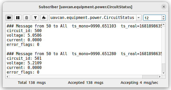
PWM-node as well as any other our nodes measures and sends 5V and Vin voltages as 2 uavcan.equipment.power.CircuitStatus (opens new window) messages
The first message has circuit_id=NODE_ID*10 + 0 and following 3 significant fields:
- voltage - is the 5V voltage
- current - is the max current for the last 0.5 seconds (supported only by
5Anode) - error_flags - might have ERROR_FLAG_OVERVOLTAGE or ERROR_FLAG_UNDERVOLTAGE or non of them
The second message has circuit_id=NODE_ID*10 + 1 and following 3 significant fields:
- voltage - is the Vin voltage
- current - is the average current for the last 0.5 seconds (supported only by
5Anode) - error_flags - ERROR_FLAG_UNDERVOLTAGE or non of them. There is no ERROR_FLAG_OVERVOLTAGE flag because the expected max Vin voltage is unknown.

4.1.2. Device temperature
The node measures and sends device temperature as uavcan.equipment.device.Temperature (opens new window) message.

If the temperature goes above 60 °C, the controller will automatically decrease the maximum intensity.
If the temperature goes above 80 °C the leds will be disabled for the safety purpose.
Typically, it's not an issue if you use only one color of the leds (red, blue or green) even with the highest intensity. But the overheat may appear if you use white color because it forces RGB leds to use all 3 internal leds.
4.1.3 Log messages
The node may inform you when something happen using uavcan.protocol.debug.LogMessage (opens new window).
At that moments the node may publishes messages only 5 second after enabling. Here we can have one of following messages:
- If everything is ok, the log level is
DEBUGand the message issys inited - If the node have power problems, the log level is
ERROR, - If the hardware and software diagnostic fails during initialization, you will get a
CRITICALlevel message. This should not happen in normal condition, but if so, don't use it in production. In this case, the node repeats the message each 15 seconds.
A visualization of this message in gui_tool in case of error shown on a picture below.
Fig. Visualization of log messages in uavcan_gui_tool after initialization with log_level=0
This message might be used in PX4 as logmessage (opens new window) feature.
# 4.2. DroneCAN parameters
Below you can see a picture from gui_tool with a whole list of parameters.
Configuration of mapping can be performed using gui_tool or even QGC. Below you can see the table with these params in gui_tool.

Table with parameters description:
| № | Parameter name | Reboot required | Description |
|---|---|---|---|
| 1 | log_level | true | Specify what level of log can be sent. |
| 2 | rgb_leds_max_intensity | false | Input DroneCan commands linearly scales into intensity from 0 to this value. Max value is 255. |
| 3 | rgb_leds_id | true | Id for DroneCan command that will be expected by the node. By default 0 id corresponds ui led. |
| 4 | rgb_leds_default_color | false | The color during arming state. See table below with more info. |
| 5 | rgb_leds_light_type | false | The type of lighting during arming state. It might be solid, blink or pulsing lighting. See table below with more info. |
| 6 | rgb_leds_num_of_leds | true | Number of leds on the board. |
| 7 | rgb_leds_blink_period_ms | false | Make sense only when rgb_leds_default_color is 1. |
| 8 | rgb_leds_blink_duty_cycle_pct | false | Make sense only when rgb_leds_default_color is 1. |
Table with default colors:
| № | Color |
|---|---|
| 0 | red |
| 1 | green |
| 2 | blue |
| 3 | magenta |
| 4 | yellow |
| 5 | cyan |
| 6 | white |
| 7 | turned off |
Table with lights types:
| № | Type |
|---|---|
| 0 | solid |
| 1 | blink |
| 2 | pulsing |
# 4.3. Getting started (bench test)
Before mounting on a real vehicle, especially when using the node for the first time, it is recommended to test the node and perform configuration on a bench using gui_tool (opens new window).
The following checklist allows you to test most of the features and configure the most important parameters.
gui_tool doesn't support sending LightsCommand (opens new window), so you can test only part of the features.
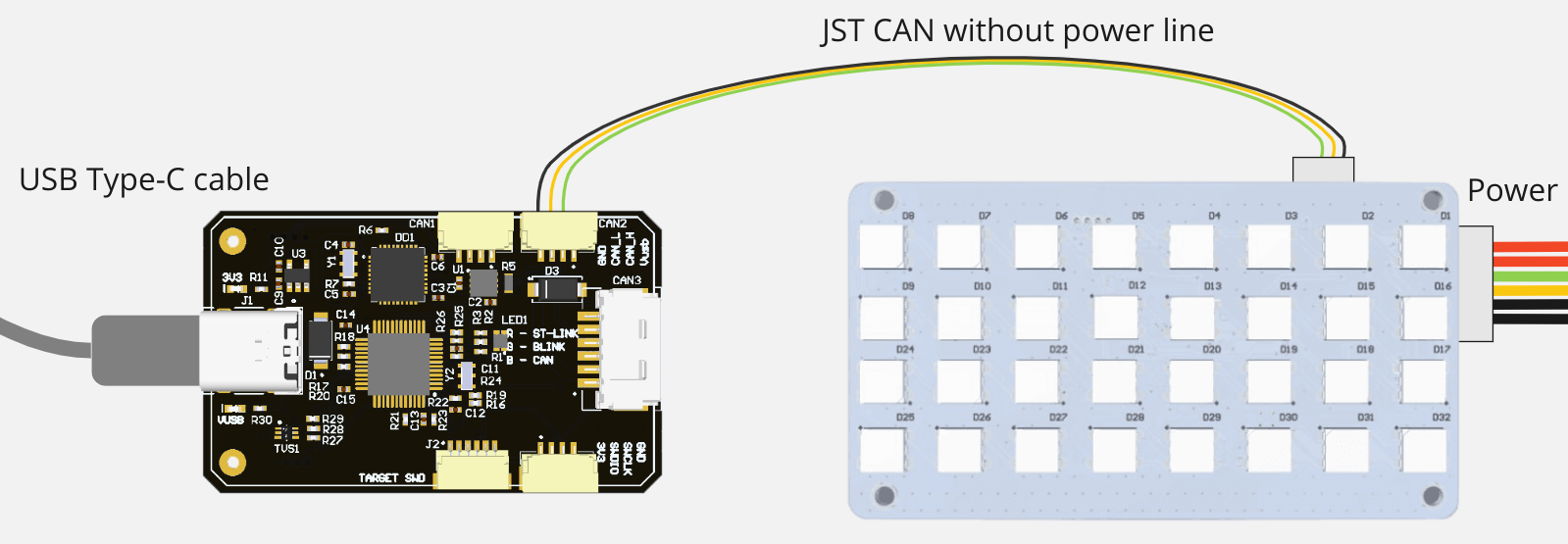
Step 1. Connect the node properly to a sniffer.
The simplest connection scheme just for bench testing and configuration is shown below.

However, the node may consume a lot of power when all 3 colors (red, green, blue) are enabled with the hightness brigtness, so it is recommended to use the following connection scheme where you power a node from an external source (up to 30V) to a Molex (6-pin) connector and connect the sniffer to the JST-GH 4-pin connector. The connection scheme is:
WARNING
Remove the 5V (red) line from the JST wire on the connection scheme below!

In progress: new version of the software will have automatic detection of the connection type. If you power from JST (5V), it will automatically reduce the brightness to reduce the power consumption, so it can be easily and safely used with any connection type.
Step 2. Open gui_tool and set the local node ID. The node should send data and respond to GetNodeInfo
Apply the Local Node ID by clicking the button in the corresponding field at the top.
Open gui_tool and check that the node publishes some data like NodeStatus and GetNodeInfo. You can quickly press 2 times on the node in Online nodes list. You should be able to see additional information such as node name, software version, UID, etc.
The node should respond with the software version that suits you (probably it should be the latest available stable version).
The typical node info response might visualized as follows:

If your node doesn't send
GetNodeInfoit probably means that your gui_tool is still in anonymous mode. Apply local node ID.
Step 3. Configure the node ID and name, Store parameters, then reboot it. ID value and name should be updated.
Select the node ID by changing uavcan.node.id that fits your CAN-network without ID-collision.
The name is optional thing. It should help you to identify it among other similar nodes. Change it by typeing new name in name parameter.
Step 4. Check CircuitStatus. The node should measure the input voltages and temperature correctly.
Use Tools > Subscriber to look at topics.
If you power a node from USB, the voltage should be ~5V.
The temperature may be significantly higher than in your room. All 3 activated RGB LEDs with the highest brigtness consume enough power to heat the board up to ~80 °C. It should not be a problem because the board has an software regulator that automatically decrease the brigtness if the temperature is higher than 60 °C. The regulator will forcibly disable all LEDs if temperature is higher than 80 °C.
Step 5. Configure RGB LEDs related parameters, save paramers and press the reboot button. The node should apply the desired settings.
Typically, you need 3 configureation types.
- If you need a solid red color, the default configuration should be enough:
| Parameter | Value | Meaning |
|---|---|---|
| rgb_leds_first_color | 0 | Red color |
| rgb_leds_light_type | 0 | Solid |
- If you need a solid green color, try the following configuration:
| Parameter | Value | Meaning |
|---|---|---|
| rgb_leds_first_color | 1 | Green color |
| rgb_leds_light_type | 0 | Solid |
- If you need a blinking white, try the following configuration:
| Parameter | Value | Meaning |
|---|---|---|
| rgb_leds_first_color | 6 | White color (all LEDs) |
| rgb_leds_second_color | 7 | Turned off |
| rgb_leds_light_type | 1 | Blink |
| rgb_leds_blink_period_ms | 1000 | 1000 ms |
| rgb_leds_blink_duty_cycle_pct | 10 | 10 % |
# 4.4. PX4 integration
You can integrate this node with PX4 by performing following steps:
- According to the PX4 user guide the
UAVCAN_ENABLEmust be set to one of the non-zero values. - You need to manually set node id to each nodes you are going to use.
- You might be interested in configuration the following parameters as well:
UAVCAN_LGT_ANTCL,UAVCAN_LGT_LAND,UAVCAN_LGT_NAV,UAVCAN_LGT_STROB.
# 4.5. Software versions
32-led board:
| Version | Date | Description |
|---|---|---|
| v0.6.4_d750b3e (opens new window) | Jun 7, 2022 | Known issue: the version is displayed as v0.5 |
| v0.5.8_e60ccf2 (opens new window) | May 06, 2022 |
15-led board (legacy):
| Version | Date | Description |
|---|---|---|
| v0.7.5_c71254c (opens new window) | Aug 4, 2022 | |
| v0.3.9_57dc7a6 (opens new window) | Oct 28, 2021 |