# 2. Hardware
This page is about hardware specific details. For general information, refer to the 1. General page., for software related details please refer DroneCAN interface.
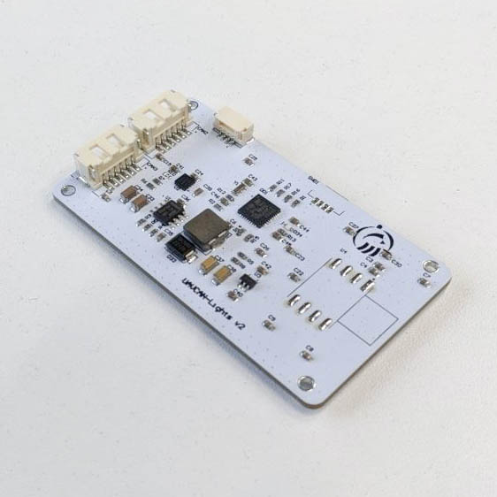
| View | Top | Bottom |
|---|---|---|
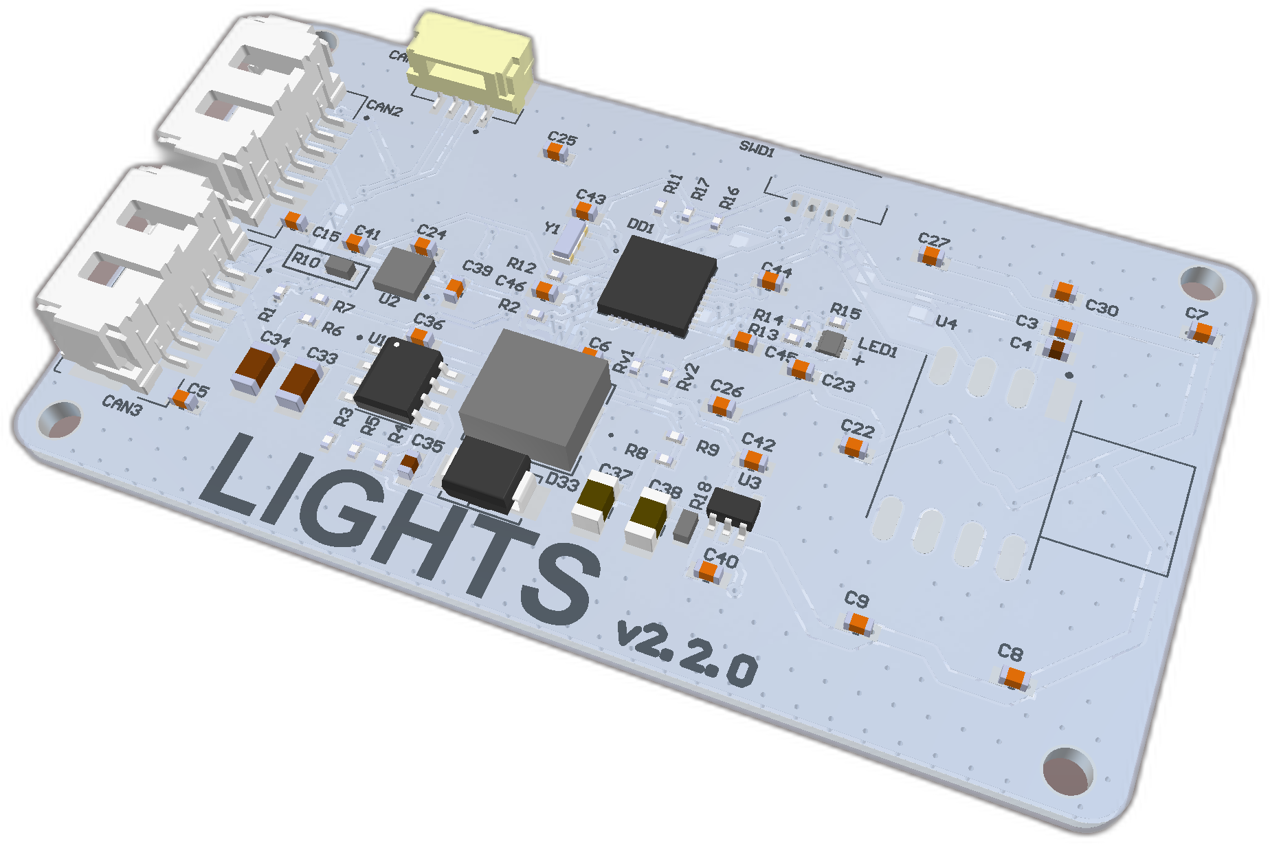 | 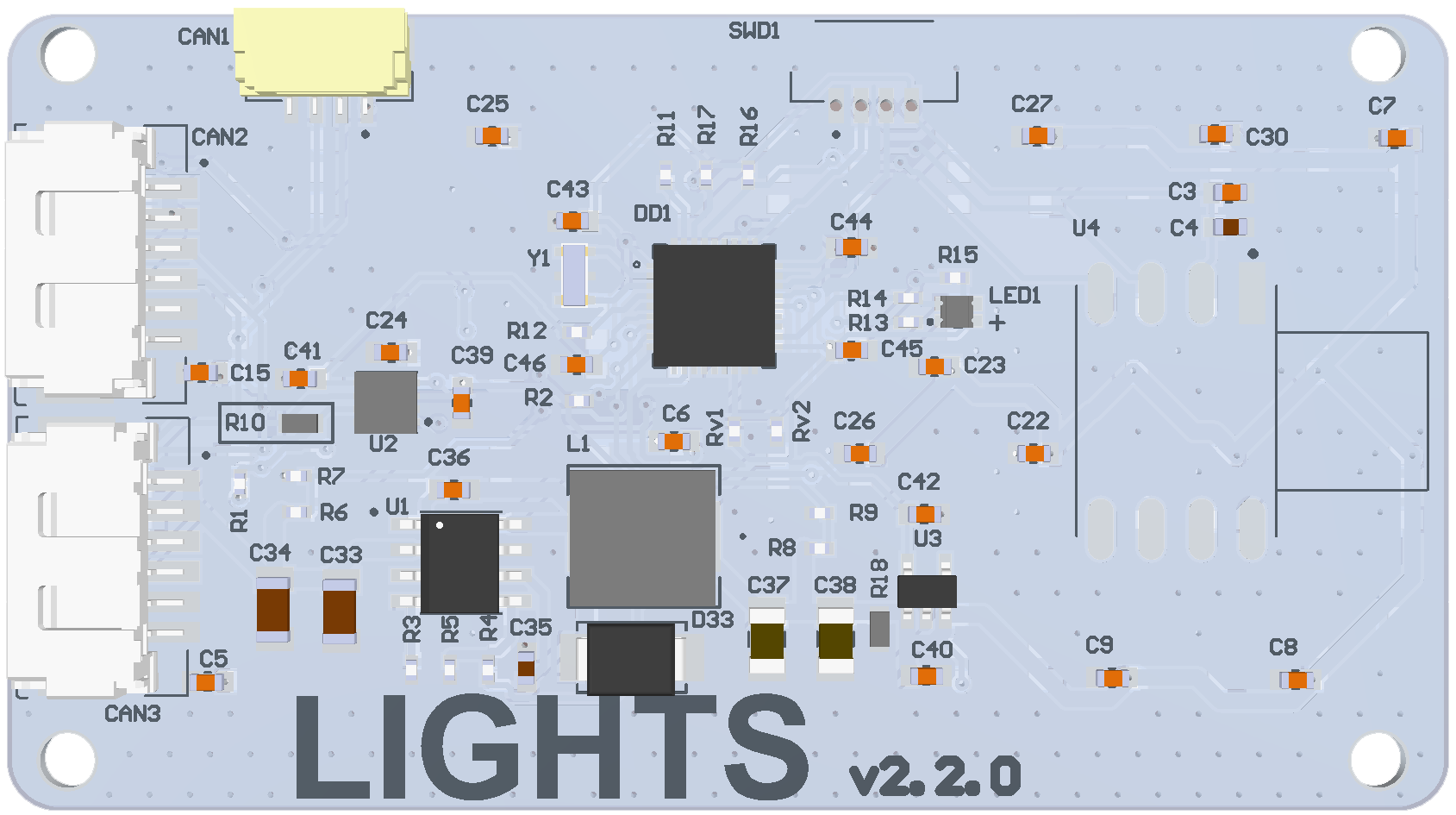 |  |
 | 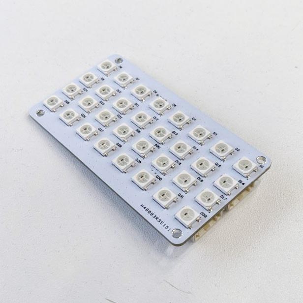 |
# Features
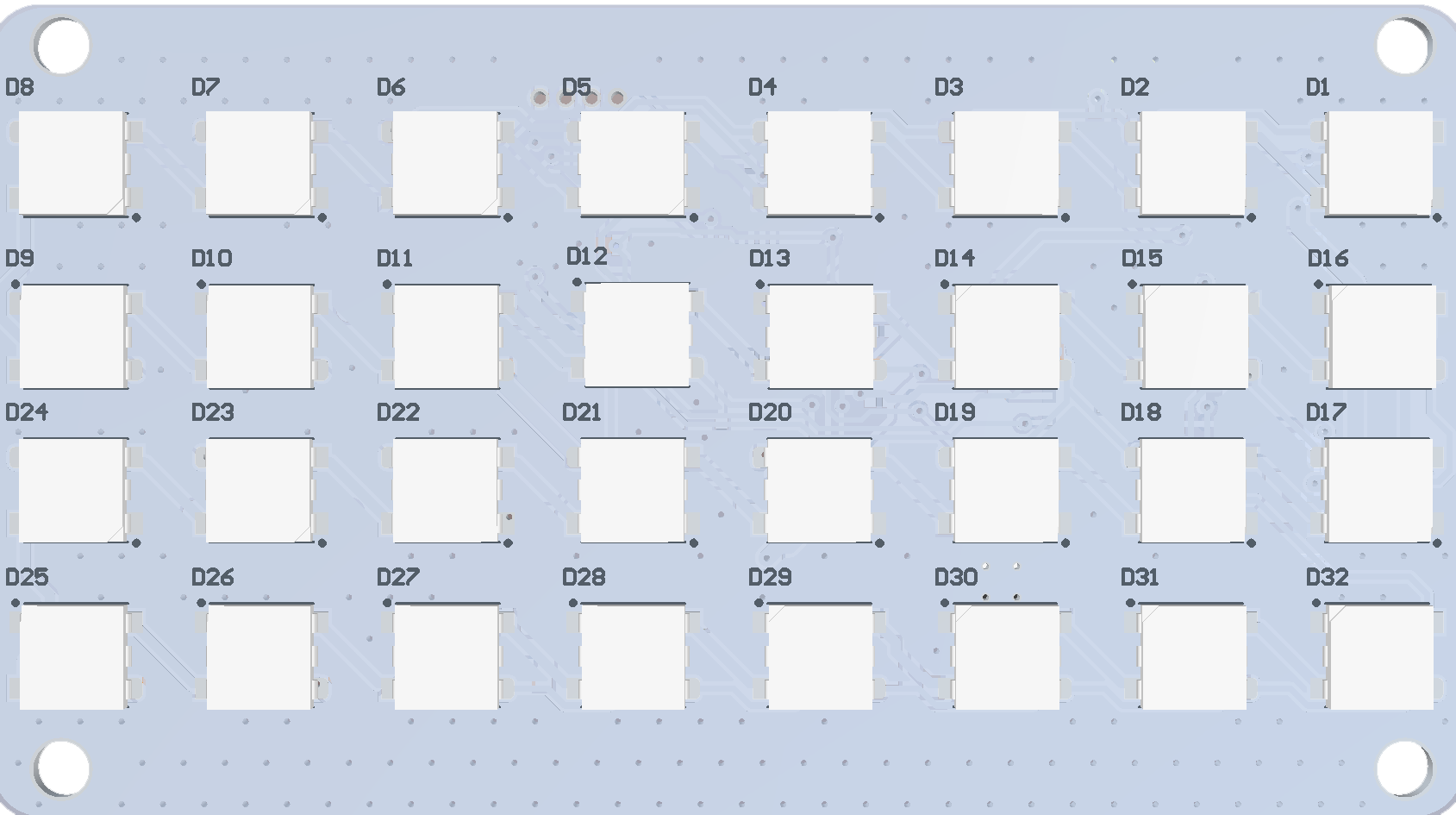
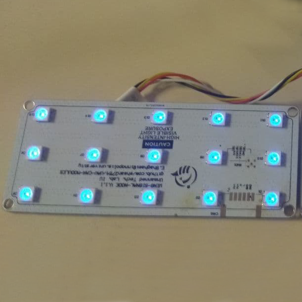
- 32 RBG LEDs
- Powered by a wide range of voltages
# Wire
Schematic features. Schematic can be provided via issue.
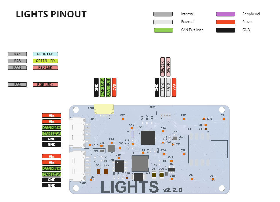
Connectors
The node has connectors which are described in the table below.
| N | Connector | Description |
|---|---|---|
| 1 | CAN1 | 5 V power up CAN bus connector |
| 2 | CAN2, CAN3 | 6-30 V power up CAN bus connector |
| 3 | SWD1 | STM32 firmware updating using programmer-sniffer |
Here (opens new window) you can find manufacturer part number of connectors it self and its mates.
# 2.1 Pin configuration and functions
| Pin N | CAN1 | Pin N | CAN2,CAN3 | Pin N | SWD1 |
|---|---|---|---|---|---|
| 1 | 5V | 1 | Vin | 1 | GND |
| 2 | CAN_H | 2 | Vin | 2 | SWLK |
| 3 | CAN_L | 3 | CAN_H | 3 | SWDIO |
| 4 | GND | 4 | CAN_L | 4 | 3.3 |
| 5 | GND | 5 | |||
| 6 | GND | 6 |
Here you can see all connections of device.
You can find configured file for MCU in lights-v2-software (opens new window) repo. MCU pinout can pe represented as picture and table below.

| MCU PIN | PIN Numer | NET Name | Description |
|---|---|---|---|
| PB1 | 16 | VERSION | |
| PA14 | 28 | SWLK | |
| PA13 | 25 | SWDIO | |
| PB7 | 34 | SDA | Airspeed |
| PB6 | 33 | SCL | Airspeed |
| OSC_OUT/PD1 | 3 | OSC_OUT | |
| OSC_IN/PD0 | 2 | OSC_IN | |
| PA15/JTDI | 29 | INTERNAL_LED_RED | Internal |
| PA4 | 11 | INTERNAL_LED_BLUE | Internal |
| PA8 | 20 | INTERNAL_LED_BLUE | Internal |
| PA2 | 9 | WS2812B_RGB_LED | LEDs contorol |
| PA12 | 24 | CAN_TXD | |
| PA11 | 23 | CAN_RXD | |
| PA0-WKUP | 7 | ADC_VIN | |
| PA1 | 8 | ADC_5V |
# 2.2 Specifications
Mechanical
Scheme is shown on the picture below. CAN model can be provided via email request or issue on github or downloaded on GrabCAD (opens new window) (opens new window).
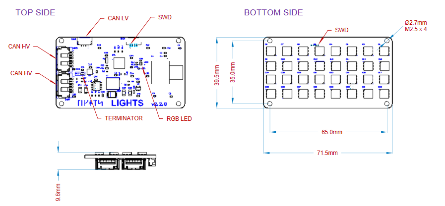
| Width, mm | Length, mm | Height, mm | |
|---|---|---|---|
| Outline | 71.5 | 39.5 | 9.6 |
| PCB | 71.5 | 39.5 | 1.6 |
Total weight of device is 16.1 g.
# Housing
Information about case is not presented.
# Absolute Maximum Ratings
| Parameter | MIN | MAX | UNIT |
|---|---|---|---|
| Vin (HV) | 5.5 | 55* | V |
| V (LV) | 4.5 | 5.5 | V |
| I max | 1.0 | A | |
| Operating temperature |
*Noted Voltage should be delivered only with current limitation under 2.5 Amp.
# Recommended operating conditions
| Parameter | Value | UNIT |
|---|---|---|
| Vin (HV) | 30 | V |
| V (LV) | 5 | V |
| I max @ 30V | 0.260 | A |
# ESD ratings
| Description | Value | UNIT |
|---|---|---|
| Human-body model (HBM) | 2000 | V |
| Charged-device model (CDM) | 500 | V |
# MTFF
Not presented for now.
# 2.3 Integration
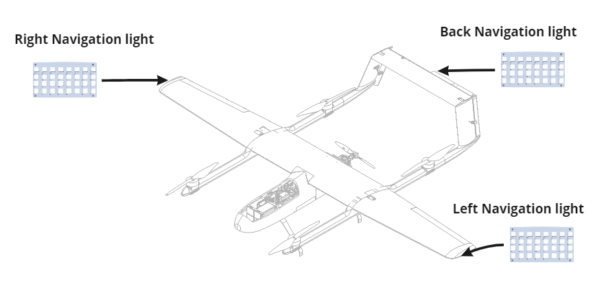
Recommended mechanical mounting
There are no specific recommendations. However, in general the navigation lights should be placed at the very end of each wing and tail.
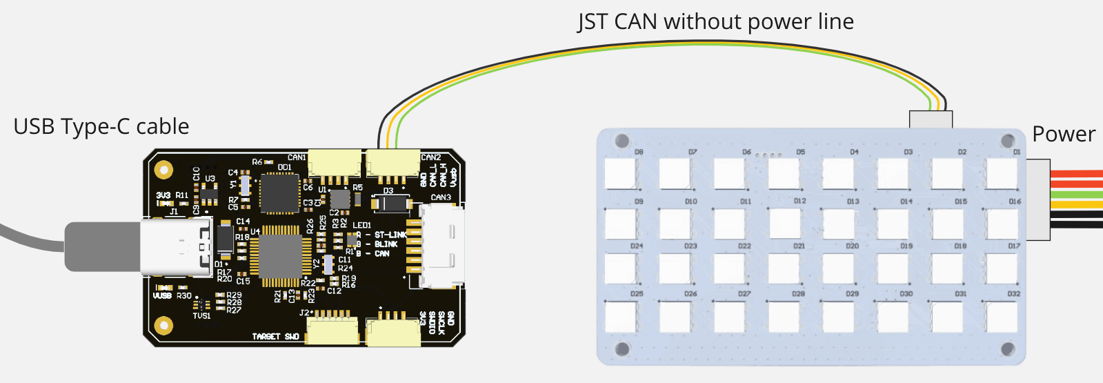
Connection example diagram
To display the status of the autopilot, this board should be connected to one of the autopilot's CAN ports.
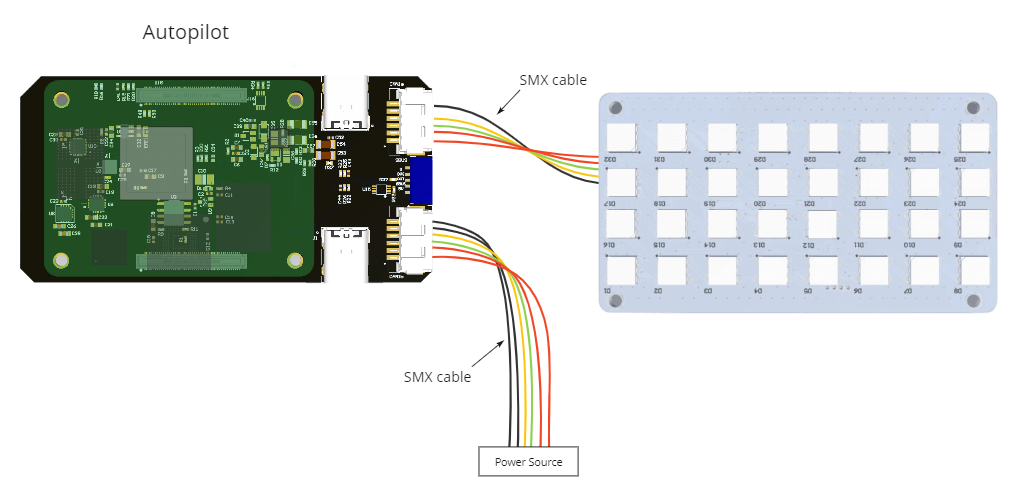
Alternatively, this device can be connected to Sniffer and controlled manually from the GUI tool.
# Power Supply Recommendations
Device is designed to operate from an input voltage supply range between 4.5 V and 5.5 V over CAN1 connector, or 5.5 - 30 V from CAN2,3. This input supply must be able to withstand the maximum input current and maintain a stable voltage. The resistance of the input supply rail should be low enough that an input current transient does not cause a high enough drop that can cause a false UVLO fault triggering and system reset. The amount of bulk capacitance is not critical, but a 47-uF or 100-uF electrolytic capacitor is a typical choice.
# 2.4 Revision history
| View | Version | Date | Description |
|---|---|---|---|
| v2.2 (opens new window) | Oct 15, 2023 | RGB led for status indication added |
 | v2.0 (opens new window) | Nov 21, 2022 | 32 LEDs instad of 16 |
 | v1.1 (opens new window) |