# DroneCAN BMS node
BMS node reads data from BMS 16i (opens new window) and sends it as DroneCAN message.
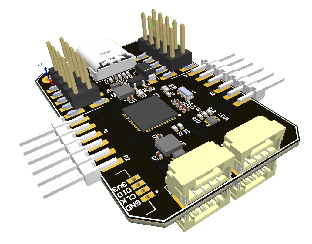
# 1. Hardware specification

# 2. Wire
The node has several connectors which are described in the table below.
| № | Connector | Description |
|---|---|---|
| 1 | CAN1A, CAN1B (UCANPHY Micro or JST-GH 4) | This CAN socket is used for communication with DroneCAN/Cyphal network. The baudrate is 1000000. |
| 2 | CAN2A, CAN2B (UCANPHY Micro or JST-GH 4) | This CAN socket is used for reading data from BMS. The baudrate is 250000. |
| 3 | SWD | STM32 firmware updating using programmer-sniffer. |
| 4 | USB | Do not use it. |
BMS 16i is powered directly from the monitored battery and works independently.
Example of connection is shown below.

# 3. Main function description
The node converts CAN frames from the BMS 16i in his format on the CAN2 socket and sends DroneCAN BatteryInfo on the CAN1 socket.
The node reads 3 CAN frames from the BMS (package0, package1 and package2).
The reading data are:
- total voltage,
- total current,
- temperature,
- 3 flags: bms error, is used and overheat.
The node also estimates an average power and charging level in percents.
The result publish rate is 3 Hz. More specifically, the node sends message when it received something from the BMS. If there is no data, the node will send nothing.
3.1 Charging level
There are 2 option how to fill the charging level.
If bms_estimate_percent is disabled (= 0), the node parses this value from the BMS directly.
If bms_estimate_percent is enabled (= 1), the node linearly estimates this value himself. You should specify the following parameters:
bms_cell_num,bms_cell_min_voltage_mv,bms_cell_max_voltage_mv,
If total voltage is less than bms_cell_num * bms_cell_min_voltage_mv, the charging level will be 0%.
If total voltage is more than bms_cell_num * bms_cell_max_voltage_mv, the charging level will be 100%.
Otherwise the charging level will be linearly estimated between 0 and 100%.
# 4. Led indication
This board has an internal led that may allow you to understand possible problems. It blinks from 1 to 10 times within 4 seconds. By counting the number of blinks you can define the code of current status.
| Number of blinks | Color | Health | Description |
|---|---|---|---|
| 1 | Green | OK | Everything is ok. |
| 5 | RED | ERROR | Either the node receive nothing from BMS for at least 1 second or it receive ERROR status |
| 6 | RED | CRITICAL | There is a problem on the periphery initialization level. Probably you load the wrong firmware. |
# 5. DroneCAN Interface
Device get info from i2c and publish to CAN.
| № | Type | Message |
|---|---|---|
| 1 | publisher | uavcan.equipment.power.BatteryInfo (opens new window) |
| 2 | publisher | uavcan.protocol.debug.LogMessage (opens new window) |
Besides required and highly recommended functions such as NodeStatus and GetNodeInfo this node also supports the following application-level functions:
| № | type | message |
|---|---|---|
| 1 | RPC-service | uavcan.protocol.param (opens new window) |
| 2 | RPC-service | uavcan.protocol.RestartNode (opens new window) |
| 3 | RPC-service | uavcan.protocol.GetTransportStats (opens new window) |
# 6. DroneCAN Parameters
| № | Parameter name | Parameter Type | Description |
|---|---|---|---|
| 0 | id | Integer | Node identifier. Should be unique in the network |
| 1 | bms_std_addr | Integer | BMS standard CAN address |
| 2 | bms_ext_addr | Integer | BMS extended CAN address |
| 3 | bms_battery_id | Integer | Battery identifier (BatteryInfo message) |
| 4 | bms_instance | Integer | Instance (BatteryInfo message) |
| 5 | bms_power_filter_size | Integer | Moving average power estimator filter size |
| 5 | bms_cell_num | Integer | Number of cells. It is used for charging percent estimation. |
| 6 | bms_cell_max_voltage_mv | Integer | Max cell voltage. It is used for charging percent estimation. |
| 7 | bms_cell_min_voltage_mv | Integer | Min cell voltage. It is used for charging percent estimation. |
| 8 | bms_estimate_percent | Integer | Enable or disable charging percent estimation. |
| 9 | bms_self_test | Integer | Disable (0) or enable (1) self testing |
| 10 | log_level | Integer | Logging level from 0 (debug) to 3 (critical only) |
| 11 | name | String | Custom node name |
# 6.1. Log level
According to the LogLevel (opens new window) message, we have 4 log levels:
- debug
- info
- warning
- errors
log_level parameter might have values described in the table below.
| Param value | DEBUG | INFO | WARNING | ERROR | Description |
|---|---|---|---|---|---|
| 0 | + | + | + | + | Log everything |
| 1 | - | + | + | + | At least INFO level |
| 2 | - | - | + | + | At least WARNING level |
| 3 | - | - | - | + | At least ERROR level |
| 4 | - | - | - | - | Disable logging |
0 - log everything, 1 - discard less than info level, 2 - discard less than warn level, 3 -log only errors, 4 - disable logging
# 6.2. Node name customization
By default this node has Unknown name. Change name parameter value to set the desired name.
# 7. Versions
Here is a list with released stable version of the firmware.
| Version | Date | SHA | Link |
|---|---|---|---|
| v0.8.12 | Oct 02, 2022 | e5bdc5c | bms_v0.8.12_e5bdc5c.bin |
| v0.8.13 | Oct 03, 2022 | d39df80 | bms_v0.8.13_d39df80.bin |
| v0.8.15 | Oct 10, 2022 | 9a4d7f7 | bms_v0.8.15_9a4d7f7.bin |
# 8. Debug on table
It is recommended to try and configure the device with gui_tool.

# 9. PX4 integration
Enable UAVCAN and set UAVCAN_SUB_BAT to 1.
