# 2. Adapter hardware
This page is about hardware specific details. For general information, refer to the 1. General page., for software related details please refer Cyphal interface or DroneCAN interface.
| View | Top | Bottom |
|---|---|---|
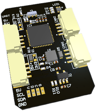 | 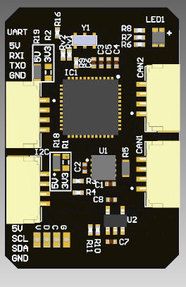 | 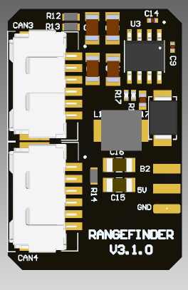 |
 | 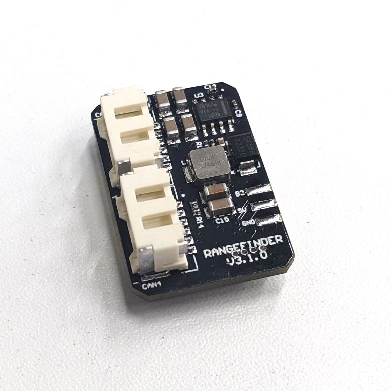 |
# 2.1 Features
- I2C port
- UART port
- 5v or 3.3v solderable jumper to power up payload
- Input voltage sensor
- 5v rail voltage sensor
- CAN connectors: 2 UCANPHY Micro (JST-GH 4) (opens new window), 2 6-pin Molex (opens new window)
- Weight: 6.6 g (with cable 8 g)
- LxWxH: 22 x 33 x 11.7 mm
# 2.2 Wire
Schematic can be provided via e-mail request or issue on github.
Connectors
| № | Connector | Description |
|---|---|---|
| 1 | UCANPHY Micro (JST-GH 4) | Devices that deliver power to the bus are required to provide 4.9–5.5 V on the bus power line, 5.0 V nominal. Devices that are powered from the bus should expect 4.0–5.5 V on the bus power line. The current shall not exceed 1 A per connector. |
| 2 | 6-pin Molex (502585-0670 (opens new window), 502578-0600 (opens new window)) | Contacts support up to 100 V, 2 A per contact. But the board may work only with 2S-6S. |
| 3 | SWD | STM32 firmware updating using programmer-sniffer. |
| 4 | UART, I2C | Connectors should be used to deliver signal and power (below 1 amp) to payload such as RANGFINDER |
Here (opens new window) you can find manufacturer part number of connectors it self and its mates.
Pin configuration and functions
| Pin | 2 CAN-HV | Pin | 2 CAN-LV | SWD | I2C | UART |
|---|---|---|---|---|---|---|
| 1 | Vin | 1 | 5V in | GND | Vcc | Vcc |
| 2 | Vin | 2 | CAN High | SWCLK | SCL | RXI |
| 3 | CAN High | 3 | CAN Low | SWDIO | SDA | TXO |
| 4 | CAN Low | 4 | GND | 3.3V | GND | GND |
| 5 | GND | |||||
| 6 | GND |
# 2.3 Specifications
Mechanical
Mechanical drowing is shown on the picture below.

| Width, mm | Length, mm | Height, mm | |
|---|---|---|---|
| Outline | 22.1 | 33.1 | 11.7 |
| PCB | 22.1 | 33.1 | 1.6 |
Total weight of device is 6.6 g.
You can download 3D model on GrabCAD (opens new window)
Housing
Information about case presented here.
Absolute Maximum Ratings
| Parameter | MIN | MAX | UNIT |
|---|---|---|---|
| Vin (CAN1) | 5.5 | 55* | V |
| V (CAN2, CAN3) | 4.5 | 5.5 | V |
| I max | A | ||
| Operating temperature |
*Noted Voltage should be delivered only with current limitation under 2.5 Amp.
Recommended operating conditions
| Parameter | Value | UNIT |
|---|---|---|
| Vin (CAN3) | 30 | V |
| V (CAN1, CAN2) | 5 | V |
| I max | A |
ESD ratings
| Description | Value | UNIT |
|---|---|---|
| Human-body model (HBM) | 2000 | V |
| Charged-device model (CDM) | 500 | V |
# 2.4 Description
Functional Block Diagram
Connection example diagram
An example of Adapter node connection with LightWare LW20/C (opens new window) (doc (opens new window)) and Garmin-Lite v3 (opens new window) (doc (opens new window)) is shown below:


# 2.5 Power Supply Recommendations
Device is designed to operate from an input voltage supply range between 4.5 V and 5.5 V over CAN2 or CAN3 connector, or 5.5 - 30 V from CAN1. This input supply must be able to withstand the maximum input current and maintain a stable voltage. The resistance of the input supply rail should be low enough that an input current transient does not cause a high enough drop that can cause a false UVLO fault triggering and system reset. The amount of bulk capacitance is not critical, but a 47-μF or 100-μF electrolytic capacitor is a typical choice.
# 2.6 Revision history
| version | Description |
|---|---|
| v3.1.0 | Initial version with STM32G0 MCU |