# 6. DroneCAN Interface
This page is about DroneCAN related details such as interface, supported features, parameters, configuration and usage examples and software versions. For general information, refer to the 1. General page., for hardware related details including connection example scheme please refer 2. Adapter Hardware.
This section is related to the latest released version of the software.
# 6.1. DroneCAN Interface
This node interacts with following messages:
| № | Type | Message | Rate |
|---|---|---|---|
| 1 | publisher | uavcan.equipment.range_sensor.Measurement (opens new window) | 10 - 100 Hz |
| 2 | publisher | uavcan.equipment.power.CircuitStatus (opens new window) | 2 Hz |
Besides required and highly recommended functions such as NodeStatus and GetNodeInfo this node also supports the following application-level functions:
| № | Type | Message |
|---|---|---|
| 1 | RPC-service | uavcan.protocol.param (opens new window) |
| 2 | RPC-service | uavcan.protocol.RestartNode (opens new window) |
| 3 | RPC-service | uavcan.protocol.GetTransportStats (opens new window) |
# 6.2. DroneCAN Parameters
The node has the following DroneCAN related registers:
| № | Register name | Description |
|---|---|---|
| 1 | uavcan.node.id | Defines a node-ID. Allowed values [0,127]. |
| 2 | system.name | Defines custom node name. If empty, the node will use the default name. |
| 3 | uavcan.node.description | User/integrator-defined, human-readable description of this specific node. |
| 4 | system.internal | Reserved |
| 5 | system.protocol | Defines the protocol: 0 - Auto (always DroneCAN at the moment) 1 - Cyphal 2 - DroneCAN |
| 6 | range.type | Defines which sensor to use: 0 - LW20/C (i2c) 1 - TF-Luna (uart) 2 - Garmin lite v3 (i2c) 3 - vl53l0x (i2c) |
| 7 | range.dronecan_sensor_id | sensor_id in DroneCAN Measurement (opens new window) message |
Generated on Dec 03, 2023 for rangefinder_v1.6.0_e30e0394.
# 6.3. Getting started (bench test)
Before mounting on a real vehicle, especially when using the node for the first time, it is recommended to test the node and perform configuration on a bench using gui_tool (opens new window). This utility allows to easily use the full functionality of the node.
Step 1. Connect the node to a sniffer. The node should blink.
An example of connection scheme just for bench testing and configuration is shown below.
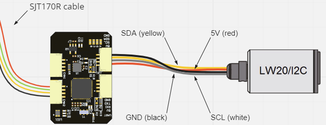
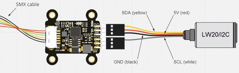
Alternatively, in a vehicle you may want to connect the node via Molex CAN connector.
By the LED color you can determine the node state:
- Orange blinking means either something is not properly configured or something wrong.
- Red blinking means some critical error. It is related to a software or hardware issue.
- Normally, the node should blink with blue color.
Please, refer to the LED meaning page (opens new window) for details.
Step 2. Open gui_tool and set the local node ID. The node should send data and respond to GetNodeInfo
Open gui_tool. Apply the Local Node ID by clicking the button in the corresponding field at the top. Check that the node publishes some data like NodeStatus and GetNodeInfo. Basically, it means that it should show: Name, Mode, Health and Uptime.

You can quickly press 2 times on the node in Online nodes list. You should be able to see additional information such as node name, software version, UID, etc.

The node should respond with the software version that suits you (probably it should be the latest available stable version).
If your node doesn't send
GetNodeInfoit probably means that your gui_tool is still in anonymous mode. Apply local node ID.
Step 3. Configure paramters, store them and reboot the node. Paramters should be updated.
Basically, you need to interract with a few parameters only:
- Select the node ID by changing
uavcan.node_idthat fits your CAN-network without ID-collision. Default value is 50. - Choose your rangefinder sensor with
range.typeparameter.
Optionally, you can also configure the following parameters:
- Set
range.dronecan_sensor_idif you have more than 1 DroneCAN rangefinder. - Set
uavcan.node.descriptionwith a description of your node. It doesn't diractly effect on anything, but allows you to easier differentiate the nodes between each other - Set
system.nameif you want to use a custom node name. The default name isco.raccoonlab.rangefinder.
If you want to switch protocol to Cyphal, you need to set system.protocol to 1.
Stora All parameters and Reboot the node.

Step 4. Open subscriber panel. The node should publish range_sensor.Measurement.
Below you can see an example of a messages.

You can also try Tools->Plotter and create a plot with measurements.

# 6.4. PX4 integration
The node has been tested multiple times on the VTOL application with autopilot based on PX4 with defferent version (v1.12, v1.13, etc).
Step 1. Configure parameters
Typically, you need to setup the following PX4 parameters (opens new window):
- UAVCAN_ENABLE must be non zero
- UAVCAN_SUB_RNG must be Enabled
- UAVCAN_RNG_MIN
- UAVCAN_RNG_MAX
| Lidar | UAVCAN_RNG_MIN | UAVCAN_RNG_MAX |
|---|---|---|
| LightWare LW20/C | 0 | 100.0 |
| Benewake TFmini LiDAR | 0 | 12.0 |
| Garmin Lidar-Lite | 0 | 40.0 |
Reboot the vehicle after the configuration.
Step 2. Check the distance sensor in Mavlink Inspector

Verify that max and min distances are correct and current_distance is adequate. The distance is shown in centimeters.
Step 3. Troubleshooting
If distance sensor is not appeared in Mavlink Inspector, try to repeat the previous steps.
It can be useful to run uavcan status in Mavlink Console:
- If the node is not online, it means the problem with physical connection.
- If the node is not
OKandOPERAT, it is either is not correctly configured, or it has a connection problem. - If the node is online, but the rangefinder sensor channel is not appeared, it means a problem with your PX4 configuration.
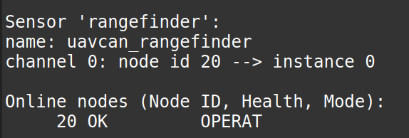
- If
uavcan statusoutput is fine, butMavlink Inspectoris not, you can try to typelistener distance_sensor. Normally, it should return something:
# 6.5. Software versions
For latest (shipping) firmware please refer to Update the firmware page.
For all avaliable for Rangefinder Cyphal & DroneCAN releases please check 1. General page.
Click here to expand Legacy (DroneCAN only) firmares
| Version | Description |
|---|---|
| v0.8.19_43c298d Oct 19, 2022 | - Add vl53l0x |
| v0.5.1_baf6e11 Feb 17, 2022 | - Add Garmin Lite v3 |
| v0.4.8_7c4d9c7 Jan 31, 2022 | - Add TF Luna support |
| v0.3.6_830e6ff (opens new window) Oct 06, 2021 | - Increase measurement rate and add filter to output |
| v0.3.0_alpha_0fe6caf (opens new window) Aug 5, 2020 | First ever released version. Only sf1xx is supported. |