# 3. uRANGEFINDER hardware
This page is about hardware specific details. For general information, refer to the 1. General page., for software related details please refer Cyphal interface or DroneCAN interface.
This device is designed to measure distance and publish it via Cyphal/DroneCAN protocols. It can be used to estimate precision landing or object avoidance.
| View | Top | Bottom |
|---|---|---|
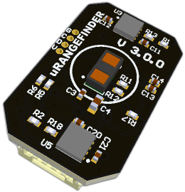 | 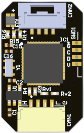 | 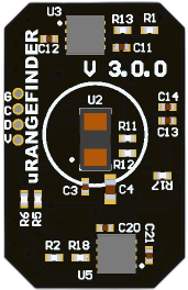 |
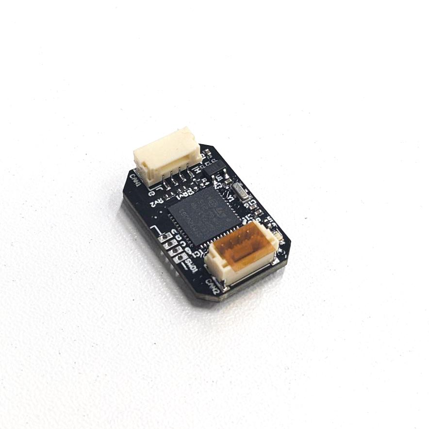 | 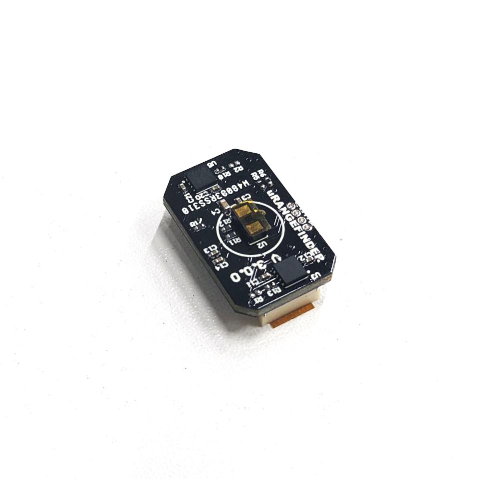 |
# 3.1 Features
- VL53L1CBV0FY-1 (opens new window) sensor
- Input voltage sensor
- CAN connectors: 2 UCANPHY Micro (JST-GH 4) (opens new window).
# 3.2 Wiring
Connectors
The node has connectors which are described in the table below.
| N | Connector | Description |
|---|---|---|
| 1 | CAN1, CAN2 | Devices that deliver power to the bus are required to provide 4.9–5.5 V on the bus power line, 5.0 V nominal. Devices that are powered from the bus should expect 4.0–5.5 V on the bus power line. The current shall not exceed 1 A per connector. |
| 2 | SWD1 | STM32 firmware updating using programmer-sniffer |
Here (opens new window) you can find manufacturer part number of connectors it self and its mates.
Pin configuration and functions
| Pin N | CAN1, CAN2 | Pin N | SWD1 |
|---|---|---|---|
| 1 | 5V | 1 | GND |
| 2 | CAN2_H | 2 | SWLK |
| 3 | CAN2_L | 3 | SWDIO |
| 4 | GND | 4 | 3.3 |
Here you can see all connections of MCU.
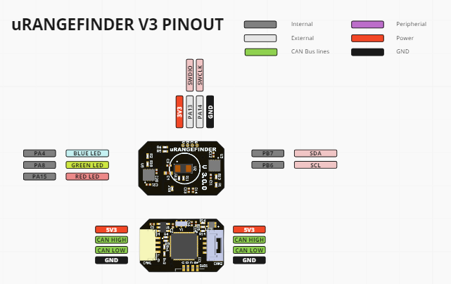
| MCU PIN | PIN Numer | NET Name | Description |
|---|---|---|---|
| PA7 | 18 | VERSION | |
| PA14-BOOT0 | 36 | SWLK | |
| PA13 | 35 | SWDIO | |
| PB7 | 46 | SDA | |
| PB6 | 45 | SCL | |
| PC6 | 30 | PC6 | |
| PC13 | 1 | LED_RED | |
| PC14-OSC32_IN | 2 | LED_GREEN | |
| PC15-OSC32_OUT | 3 | LED_BLUE | |
| PC7 | 31 | INT | |
| PB1 | 20 | FDCAN2_TX | |
| PB0 | 19 | FDCAN2_RX | |
| PD1 | 39 | FDCAN1_TX | |
| PD0 | 38 | FDCAN1_RX | |
| PA1 | 12 | ADC_5V |
# 3.3 Specifications
Mechanical
Mechanical drowing is shown on the picture below.

| Width, mm | Length, mm | Height, mm | |
|---|---|---|---|
| Outline | 14.5 | 23.0 | 7.8 |
| PCB | 14.5 | 23.0 | 1.6 |
Total weight of device is 6.6 g.
You can download 3D model on GrabCAD (opens new window)
Housing
Information about case presented here.
Absolute Maximum Ratings
| Parameter | MIN | MAX | UNIT |
|---|---|---|---|
| V (CAN1, CAN2) | 4.5 | 5.5 | V |
| I max | A | ||
| Operating temperature |
*Noted Voltage should be delivered only with current limitation under 2.5 Amp.
Recommended operating conditions
| Parameter | Value | UNIT |
|---|---|---|
| V (CAN1, CAN2) | 5 | V |
| I max | A |
ESD ratings
| Description | Value | UNIT |
|---|---|---|
| Human-body model (HBM) | 2000 | V |
| Charged-device model (CDM) | 500 | V |
# MTFF
# Integration
Recommended mechanical mounting
The most important thing is to prevent any part of the UAV from getting in front of the sensor. And it is important not to forget to remove the protective film from the sensor.
Functional Block Diagram
Not yet available.
Connection example diagram
# 3.5 Power Supply Recommendations
Device is designed to operate from an input voltage supply range between 4.5 V and 5.5 V over CAN2 or CAN3 connector. This input supply must be able to withstand the maximum input current and maintain a stable voltage. The resistance of the input supply rail should be low enough that an input current transient does not cause a high enough drop that can cause a false UVLO fault triggering and system reset. The amount of bulk capacitance is not critical, but a 47-μF or 100-μF electrolytic capacitor is a typical choice.
# 3.6 Revision history
| version | Description |
|---|---|
| v3.0.0 | Initial version with STM32G0 MCU |