# Update the firmware
WARNING
This guide is legacy. It is recommended checking the new one
This is a step-by-step guide on how to upload the latest firmware to the RaccoonLab nodes.
WARNING
For safety reasons, do not update the actuator-related nodes such as Mini or Micro on a UAV equipiped with propellers or other moving surfaces!
# Step 1. Download firmware
Please refer to the table below to determine the latest version of the shipping firmware:
| Device | DroneCAN firmware | Cyphal firmware |
|---|---|---|
Airspeed  | v0.4.5 (opens new window) | v1.4 (opens new window) (Jun 19, 2023) |
GNSS v2.5 (L1 NEO-M8M) 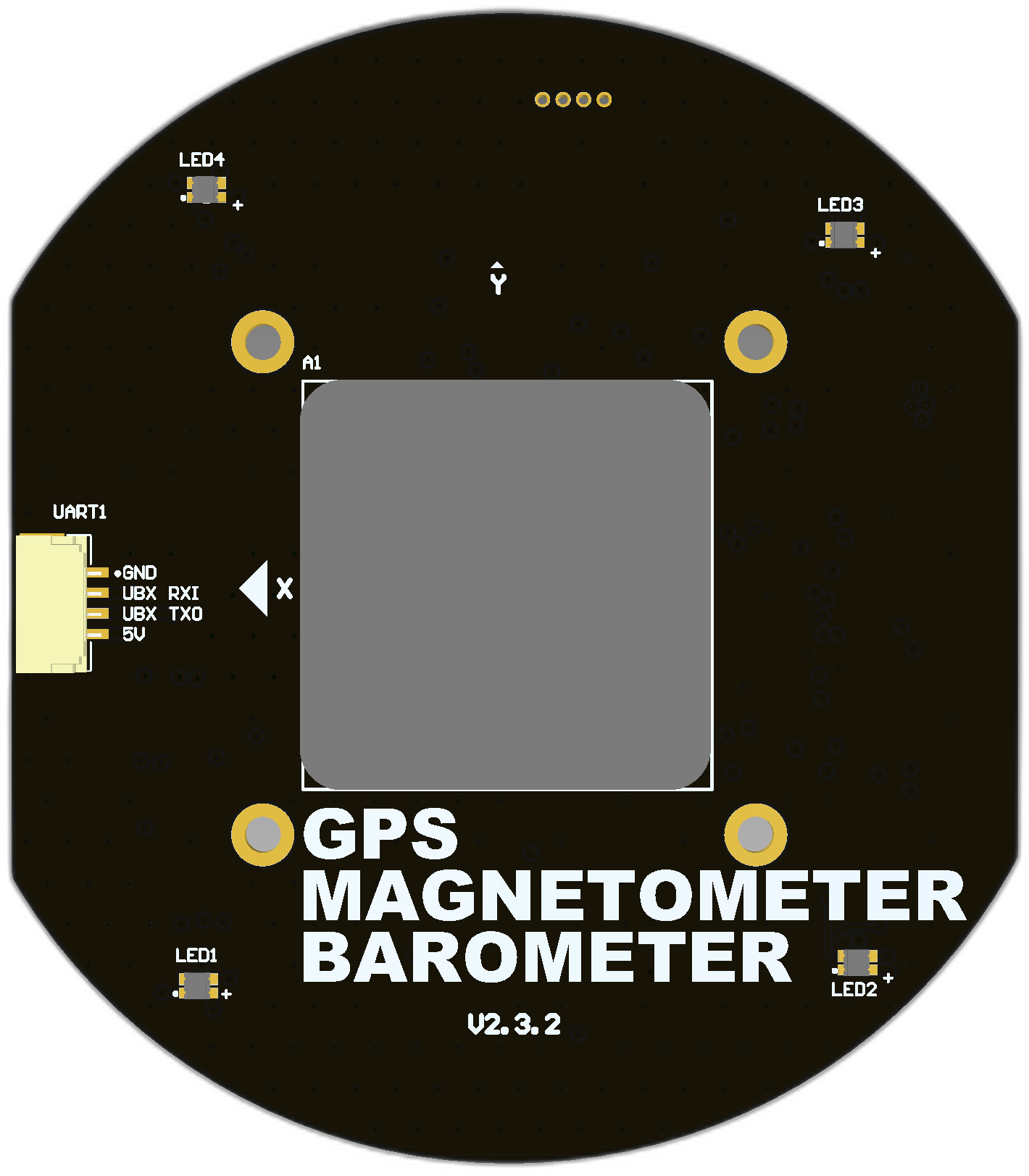 | v0.10.19 (opens new window) (v0.11 is coming soon) | v1.6.5 (opens new window) (Dec 19, 2023) |
GNSS v3 (L1/L2 ZED-F9P) 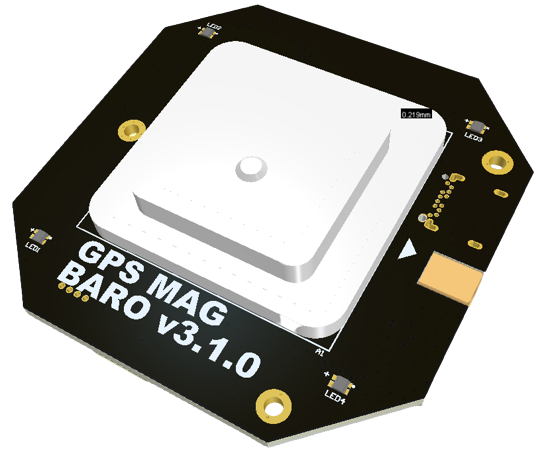 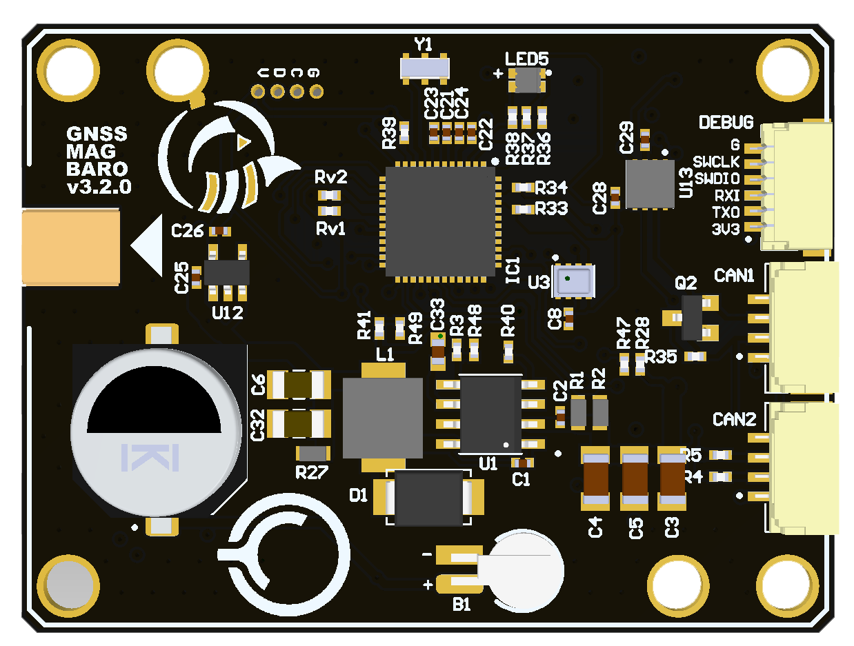 | - | v1.5.4 (opens new window) (Sep 19, 2023) |
Mini and Micro nodes 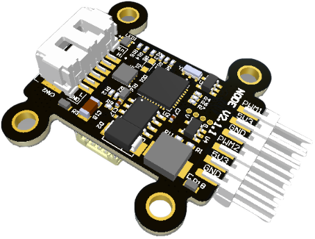 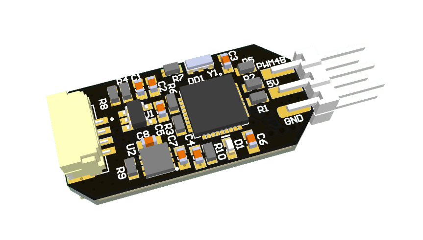 | v0.12.2 (opens new window) (Aug 09, 2023) | v1.5.10 (opens new window) (Nov 17, 2023) |
UAV Lights 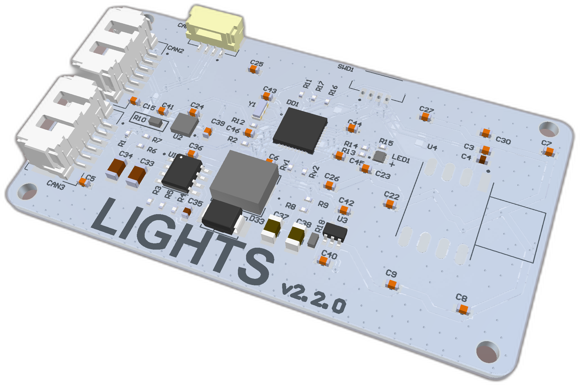 | v0.8.8-stable (opens new window) (Jun 7, 2022) | v0.2.3 (opens new window) (Dec 27, 2023) |
| Device | Cyphal & DroneCAN firmware |
|---|---|
Rangefinder nodes (opens new window) 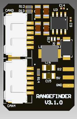 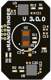 | v1.6.2_a18ac959 (opens new window) (Dec 04, 2023) |
Here a binary typically has the following name pattern: protocol>_<node_name>_<software_version>_<git_hash>.bin. An example of binary name is: dronecan_micro_v0.12.2_0601cb2.bin.
If you want to upload the latest stable firmware or get information about change history, you should check Software Versions page related to the desired board.
# Step 2. Install software
# 2.1. Windows
Install STM32CubeProgrammer (opens new window) to the default directory.
# 2.2. Linux
At the moment of writing, the latest stable version of ST-link software from APT is v1.7.0 on Apr 25, 2021 and it doesn't support STM32G0B (Chip-ID 0x467) (opens new window). Instead of using binary releases, follow the instructions from the official st-link manual on Compiling from sources (opens new window).
Here's a summarized version for a quick setup:
Remove Older Versions: Make sure you uninstall any older versions of st-link on your system.
sudo apt remove --purge libstlink1 stlinkClone the Latest st-link Repository: Clone the official st-link repository from GitHub.
git clone https://github.com/stlink-org/stlink.gitInstall libusb
sudo apt-get install git make cmake libusb-1.0-0-devBuild and Install: Navigate into the cloned directory and install the software.
cd stlink/
make release
sudo make install
sudo ldconfig
# Step 3. Connect the programmer
You have 3 options here:
- RaccoonLab Programmer-Sniffer,
- Dronecode Probe (opens new window),
- ST-LINK/V2 in-circuit debugger/programmer for STM8 and STM32 (opens new window).
TIP
Be sure that your SWD pins on the node and the needle sides are connected correctly (3.3 to 3.3, GND to GND).
# 3.1. Using RaccoonLab Programmer-Sniffer
Prerequisites are: RL Programmer-Sniffer, SWD-NEEDLE (opens new window) and JST-GH 4 cable. An example of a connection is shown below.

TIP
SWD and CAN sockets look similar and they use the same 4-pin cable. SWD has 3.3V, but CAN has 5V. Don't mix them up.
TIP
On the RL programmer VUSB led should be orange, 3.3 led should be red, ST-link led should be blue, and blink led should blink with yellow. If they are not, probably you are making something wrong. It also may indicate that the board works incorrectly.
# 3.2. Using Dronecode Probe
Prerequisites are: Dronecode Probe, SWD-NEEDLE (opens new window) and DEBUG-WIRE.
Commonly zubax (opens new window) or black-magic (opens new window) instruction can be used.
TIP
You can make .elf file from .bin, in case if you can`t finde it in releases. Just tape next command with changing paths
arm-none-eabi-objcopy -I binary -O elf32-little --change-section-address .data=0x08000000 input.bin output.elf
Thanks to this gist (opens new window)
TIP
In case of using Dronecode Probe you should power up device from CAN port.
Firstly check GDB is installed:
- in Ubuntu
gdb firmware.elf(should be installed by default) - in Windows
arm-none-eabi-gdb firmware.elf(It can be installed from developer.arm.com/downloads (opens new window)) You will se something like this:
GNU gdb (Ubuntu 12.1-0ubuntu1~22.04) 12.1
Copyright (C) 2022 Free Software Foundation, Inc.
...
Type "apropos word" to search for commands related to "word".
(gdb)
Connect all relative to the diagram below.

Type target extended-remote /dev/ttyACM0 in case of Ubuntu and target extended-remote COM4 in case of Windows.
Apply next commands:
monitor tpwr enable- enable power railmonitor swdp_scan- scan deviceattach 1load- load firmwarequit- quit GDB
You should see something like this replyes at the end:
(gdb) monitor tpwr enable
Enabling target power
(gdb) monitor swdp_scan
Target voltage: 3.3V
Available Targets:
No. Att Driver
 1      STM32F1 medium density M3
(gdb) attach 1
Attaching to program: C:\workspace\mini_v2_node\build\obj\cyphal_example.elf, Remote target
0x0800a38e in ?? ()
(gdb) load
Loading section .data, size 0x80d8 lma 0x8000000
Start address 0x00000000, load size 32984
Transfer rate: 16 KB/sec, 970 bytes/write.
(gdb) quit
A debugging session is active.
TIP
This (opens new window) instruction can be used to work with Dronecode Probe under STM32CubeIDE.
# 3.3 Using ST-LINK
Prerequisites are: ST-LINK debugger/programmer, Female wires, Adapter, DEBUG-WIRE and SWD-NEEDLE (opens new window). Here is the connection example.

# Step 4. Upload the firmware
# 4.1 Windows
It is expected to use STM32CubeProgrammer (opens new window).
Open
STM32CubeProgrammer.Connect the programmer to the PC via USB and target device to the programmer via SWD connectors as shown on the
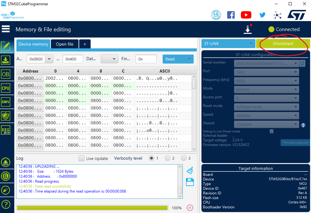
Step 3. Connect the programmer.Press
Connectbutton, you will see correspondingTarget information.Error: No debug probe detected. The programmer is not detected by your PC.Error: No STM32 target found!. The programmer is detected, but the node is not connected to programmer. It may refer to bad SWD connection between needles and the node. Try to slightly push the needles or change the connection angle.Error: Unable to list supported devices. Can't identify the device!. This error was reported once. It was gone after reinstalling the STM32CubeProgrammer software from custom to the default directory.If everything is fine, you will see the following:
Press
Open fileand choose firmware binary to be downloaded on chip. It should be the firmware binary that your downloaded inStep 1. Download firmware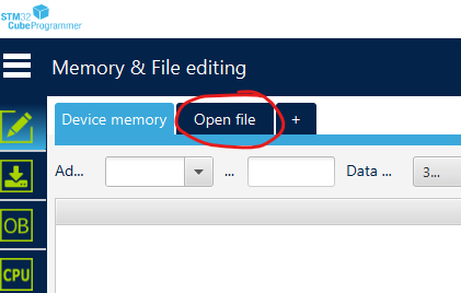
Press
Download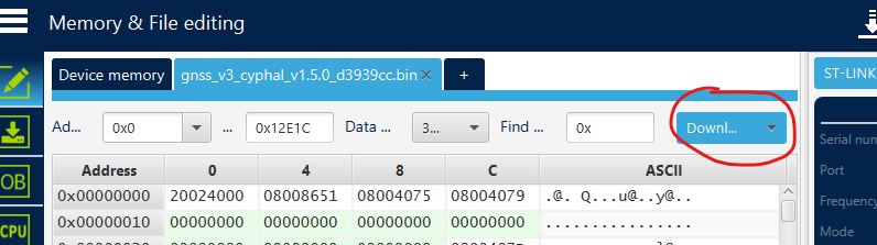
Reconnect the node
At that point, the firmware is succesfully downloaded. You can verify the software version by using gui_tool.
In case of ST-LINK utility you should follow next instructions in collapsed bar below:
DETAILS
Please expand and follow the instructions below (it has many pictures):
Install
ST-LINK utilityfrom the official site (opens new window)Open
ST-LINK utility, connect the programmer to the PC via USBConnect target device to the programmer via SWD connectors as shown on the picture above with respect to the warnings. If you gen an error, check the Windows issues section.
Choose option
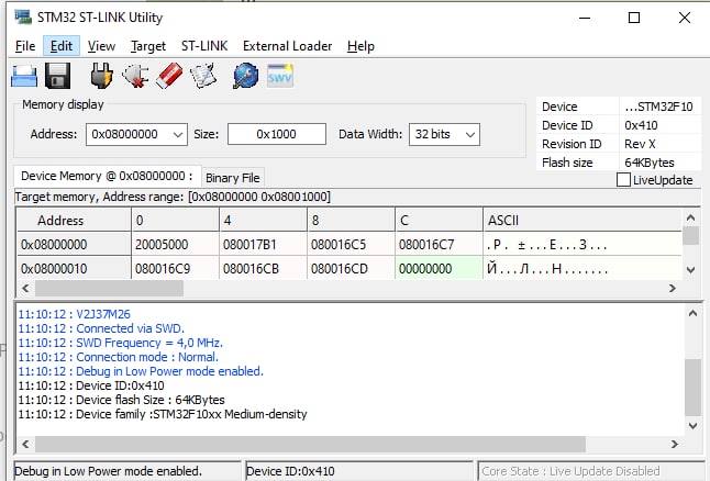
Target -> Connect. Device should be successfully connected. If you get an error, check the issues below.
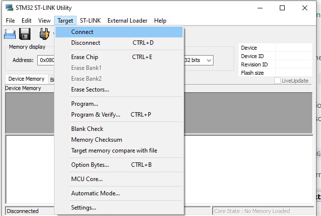
- You should see
Device IDif everything fine (as shown in picture below)
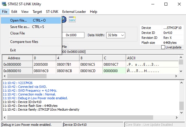
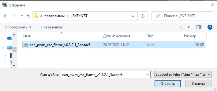
- Choose
file -> open file ...and navigate to the downloaded firmware .bin as shown in the pictures below
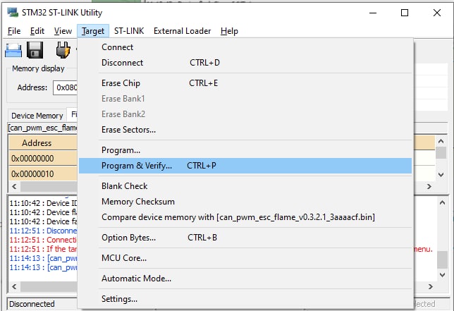
- Choose
Target -> Program & Verify ... CTRL+P
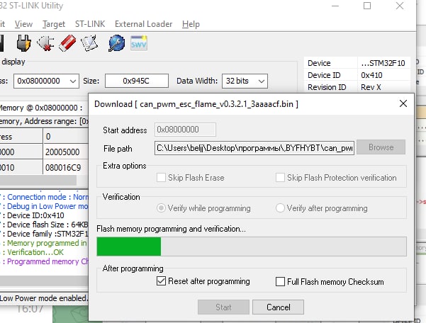
- Wait until downloading is in progress
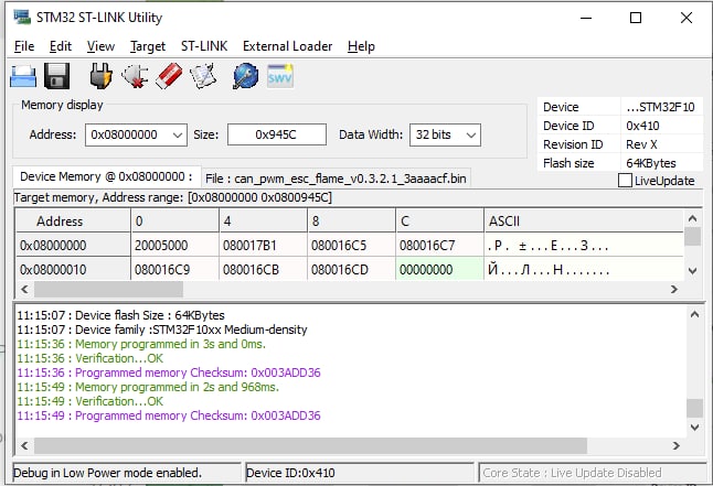
- You should see
Verification...OKif everything is ok.
At that point, the firmware is succesfully downloaded. You can verify the software version by using gui_tool.
Here is a list of the most popular issues and the recommendation how to solve them:
Wrong connection may leds to one of 2 following errors:
- Can not connect to target
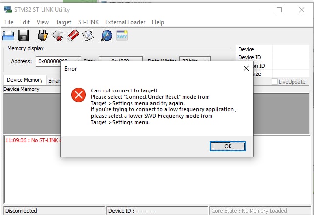
Programmer is successfully detected, but your device is not detected via SWD by the programmer. Either SWD connection is not ok, or there is a problem on the target side.
Sometimes it may happen that the 3.3 and GND are connected, but SWDIO and SWCLK are not ok enough. In this case the node blinks because it has a power, but connection is not stable enough to start a programming. Just make more tension by pushing jumpers a little bit and then press
Program & Verifyone more time.
- No ST-LINK detected
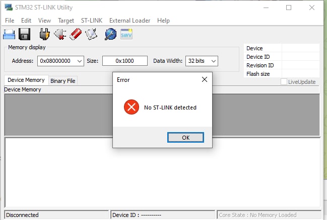
Either your programmer is not connected to your PC, or it is broken. Check the leds on the programmer device.
TIP
Its also possible to upload firmware using STM32_Programmer_CLI.exe
STM32_Programmer_CLI.exe -c port=SWD -d "<PATH_TO_FIRMWARE>\cyphal_example.bin" 0x08000000
# 4.2 Linux
It is expected to use the latest version of st-link installed from sources:
Program the Firmware:
To program the boards with stm32f103 (they all have version v2), you should explicitly specify the flash size (128 KBytes):
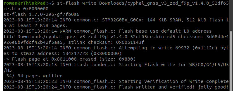
st-flash --flash=0x00020000 --reset write desired_bin_file.bin 0x8000000For boards with stm32g0 (they all have version v3), you should type:
st-flash --reset write desired_bin_file.bin 0x8000000Make sure to replace
desired_bin_file.binwith the path to your actual firmware file.Verification:
After the process completes, ensure that the firmware has been successfully uploaded (check stlink messages). Confirm that the device operates correctly.
Issues:
I have
unknown chip ID!error.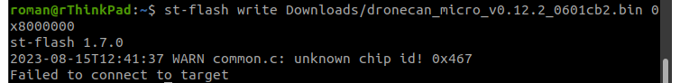
Please, install the latest version of st-link.
# Step 5. Test the device
Below you can see a brief version of testing process of the devices. It is recommended to do it every time you upload a new version of the firmware.
You can find the extended sequence of testing steps on a bench on the Getting started (bench test) section of each software type of any device. It is recommended to try them if you get a device first time to be familiar with all his specific features.
Here is list with links to the bench test instructions for the most common devices:
- Airspeed: DroneCAN (opens new window), Cyphal (opens new window)
- GNSS: DroneCAN (opens new window), Cyphal (opens new window)
- Mini and Micro nodes: DroneCAN (opens new window), Cyphal (opens new window)
Below you can see a general brief instructions.
# 5.1 Connect device
You need to connect CAN-Sniffer to your node via CAN connector and to your PC via USB. It can be either RaccoonLab Programmer-Sniffer (opens new window) or Zubax Babel (opens new window), or any other similar device.
An example of connection to RL Programmer-Sniffer (opens new window) is shown below.

# 5.2. Cyphal usage
After connection, you can use yakut (opens new window) or Yukon (opens new window) utility or something other.
On the picture below there is an example of Yukon usage.

# 5.3. DroneCAN usage
For testing DroneCAN devcies it is recommended to use dronecan/gui_tool (opens new window).
WARNING
Some Windows users say that dronecan/gui_tool doesn't work properly, so you may consider to use OpenCyphal-Garage/gui_tool (opens new window).

In the Application Setup menu you need to set 1000000 to both can bus and adapter baud rates.
After that you will get following window:

# 5.4 Make sure that device is accessible

